Diagnostic over IP(DoIP) Overview
In the blog UDS overview, I mentioned that UDS can be used with different communication layers such as CAN, Ethernet, FlexRay, and LIN. In this article, we focus on how UDS operates over Ethernet, commonly referred to as Diagnostic over IP (DoIP). 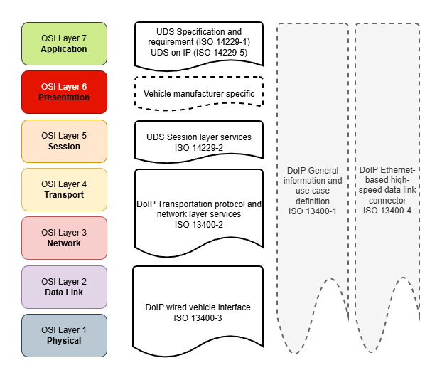
You may ask why UDS with IP, why use it over UDSonCAN and other:
- Next-gen vehicle E/E system use Ethernet as their in-vehicle network backbone.
- Ethernet provide much higher bandwidth and performance.
- Flexibility, scalability and compatibility with cloud and remote diagnostic operations.
Standard specification that provide information on Diagnostic over IP(DoIP) are:
- ISO 14229-5: Specifies IP-specific requirements for UDS services.
- ISO 13400 (Parts 1–4): Defines the DoIP protocol, covering transport, network, data link, and physical layers.
I. DoIP Architecture Overview
Diagnostic function is utilized in multiple use-cases from the vehicle development till servicing phase:
- vehicle/ECU engineering (development)
- vehicle/ECU manufacturing (production plant, assembly line)
- service (franchised dealership, aftermarket repair shop)
- legislated inspections (emissions check, safety inspections)
⟹ DoIP shall cover different communication scenarios and possible network configurations (i.e. direct or indirect, 1:n(test equipment) to 1:n(DoIP instance)).

From the network configuration setup above, we can clearly see that to support UDS application operation, the DoIP instances in the vehicle and the external test equipments must provide some core functions to establish communication channel like identification, enquiry the target nodes or provide routing for the sub-network.
Typical DoIP entities in a DoIP network:
- Edge: acts as the network interface for the entire vehicle to external test equipment, it provides physical entry point via the OBD-II connector or wireless interface, act as a firewall for vehicle DoIP network, route(application level) the external test equipment diagnostic message to/from internal vehicle network.
- Gateway: provide internal routing(network layer), facilitate the sub-network communication, and do not necessarily connect directly to the external tool.
- Node: communicate and perform the requested diagnostic functions (NOTE: should able provide diagnostic services indirectly via a gateway(routing) or with direct peer to peer connection to external test equipment).
For example, in above figure let’s assume that all internal vehicle IP-based network use IPv6 and the production external test equipment only support and communicate with DoIP Edge node of the vehicle via IPv4. In that case during the development of ECU A.2, we can either:
- implement a temporary external test equipment(tester) that establish direct connection to target ECU or
- implement a temporary Edge node simulation to provide routing for the interaction between developing ECU and actual production external test equipment.
Same approach as for the ECUs that under CAN sub-network.
II. DoIP Protocol Stack

As we can see in the diagram, Diagnostic over IP(DoIP) leverages standardized IP communication stack to enable diagnostics over Ethernet. It employ core transport protocols (TCP/UDP) and network protocols (IPv4/IPv6), alongside auxiliary components for general status inspection, address assignment and address resolution in IP network.
DoIP is intended to use with IPv6 for future proof and utilize its advantages: link local IP address assignment, faster forwarding via routers,..
IPv4 and related modules requirements are for backward compatibility in case of available DoIP nodes or test equipment that has IPv4 implementation in place.
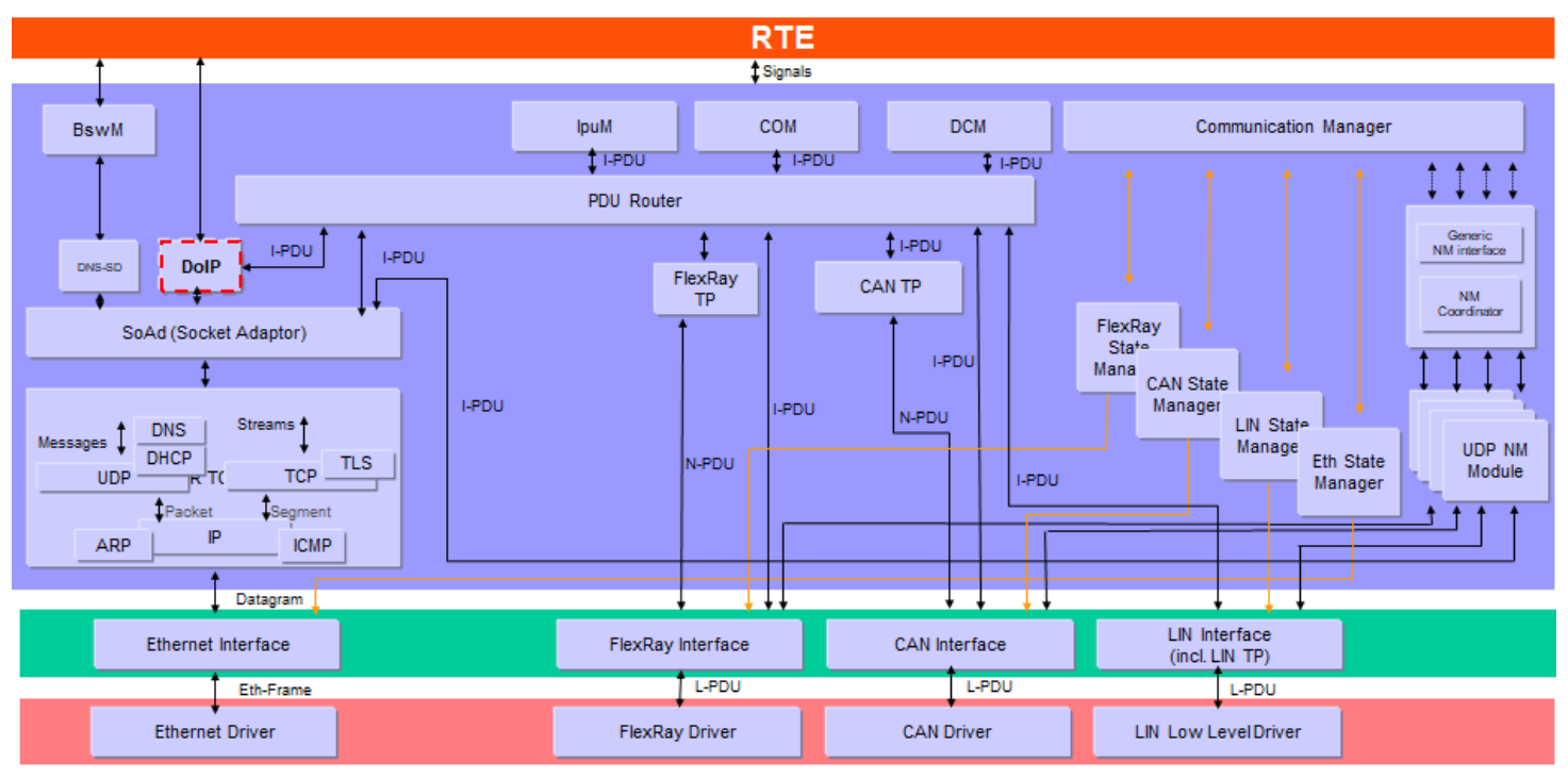
Note: Not all functionalities defined in the specified IETF RFC standards are mandatory for a DoIP node. The implementation/configuration of modules in protocol stack is depend on the specific requirements of vehicle communication (i.e. OEM specification).
This article focuses on unsecured DoIP (TCP Port 13400) as defined in ISO 13400-2:2012. Newer revisions (2019) introduce TLS security on Port 3496, but the underlying state machine logic remains similar.
Protocol Components and Requirements:
NOTE: It’s not necessary to make deep investigation into these IETF standards, but to know what IP network activities are involved and how do they work will help you with the implementation/integration and bring-up of DoIP node.
II.1. Network data transmission component
The Network Layer handles the transmission of data to target IP node. Depending on supported interfaces, DoIP stack must implement one or both of the following:
| IPv6 and IPMCv6 | IPv4 and IPMCv4 |
|---|---|
| Internet Protocol as specified in IETF RFC 2460 (Internet Protocol, Version 6). | Internet Protocol as specified in IETF RFC 791 (Internet Protocol - Protocol Specification) for legacy support. |
| Internet Control Message Protocol - ICMPv6 as specified in IETF RFC 4443 | ICMP as specified in IETF RFC 792 |
Any packets with a multi- or broadcast address as the source IP address shall be ignored.
II.2. Address resolution and assignment
To establish communication, the node must obtain an IP address and resolve IP addresses to MAC addresses, and depend on network infrastructure, used IP layer, an ECU can utilize different mechanisms or approaches such as:
- statically pre-configured IP address (except the Edge node external interface, most of vehicle ECUs internal IP interface should be statically pre-configured).
- IP address is acquired dynamically from DHCP server.
- link-local IP address by AutoIP (used as a fallback mechanism when DHCP is unavailable).
II.2.1 IP Address assignment:
If supported, vehicle DoIP entity shall only implement DHCP client behavior, and provided “host name”(“DoIP-<manufacturer_specific>”) as defined in IETF RFC 2132 or 4702.
| DHCPv6 client behavior | DHCP client behavior |
|---|---|
| for IPv6, as specified in DHCPv6 (IETF RFC 3315) | for IPv4, as specified in DHCP (IETF RFC 2131) |
To improve IPv4 address-assignment performance when no static IP address is configured, DoIP entity run DHCP and AutoIP in parallel:
- AutoIP assigns a temporary IPv4 link-local address (169.254.0.0/16) as specified in IETF RFC 3927
- If a DHCP address becomes available, the DHCP-assigned address takes precedence and replaces the AutoIP address
Same for IPv6, DHCPv6-assigned addresses also takes precedence.
In addition, every IPv6-enabled interface automatically configures a link-local IPv6 unicast address, according to:
- RFC 4291 — IPv6 Addressing Architecture
- RFC 4862 — IPv6 Stateless Address Autoconfiguration (SLAAC)
- RFC 3484 (updated spec RFC 6724) — Default Address Selection for IPv6
NOTE: While ISO 13400 mandates DHCP support, if employ the DHCP client implementation is usually available on Edge node(.e.g Gateway or Infotainment system). In practice the vehicle DoIP nodes usually utilize Auto-IP (169.254.x.x) or pre-configured with static IP to ensure determinism and fast uptime.
In addition, the timing values for IPv4 AutoIP and IPv6 SLAAC may differ from defined ones in RFC specifications .e.g probing, announcing intervals are adjusted to improve performance and better suit automotive network environments.
II.2.2 Address Resolution:
Once an IP address has been assigned, the node must resolve destination IP addresses to Ethernet MAC addresses in order to transmit frames on the link layer:
- ARP (IPv4): Define in IETF RFC 826, Address Resolution Protocol maps IPv4 addresses to MAC addresses.
- NDP (IPv6): Define in IETF RFC 4861, Neighbor Discovery Protocol replaces ARP in IPv6 and provides:
- Neighbor address resolution
- Duplicate Address Detection
- Router and prefix discovery
II.3. Data transportation
The Transport Layer manages end-to-end communication channel between the vehicle and the external test equipment.
| Transmission Control Protocol (TCP) | User Datagram Protocol (UDP) |
|---|---|
| - primary transport protocol for diagnostic data exchange. - dedicated port TCP_DATA (13400) shall be used for DoIP’s TCP connection(i.e. as remote port for transmission or as local port for receiving). - DoIP entity shall support n+1 TCP sockets, where n represents the number of concurrent diagnostic sessions required. | - primarily used in vehicle discovery, identification phase and status enquiry. - Vehicle’s DoIP entity shall listens on UDP_DISCOVERY (13400) for identification requests from test equipment. - Vehicle’s DoIP entity transmit unsolicited “Vehicle Announcement” messages to UDP_DISCOVERY (13400) to notify its presence on the network to test equipment. - only one DoIP message per UDP datagram |
| IETF RFC 793, IETF RFC 1122, IETF RFC 6298(IPv6) | IETF RFC 768, IETF RFC 1122 |
NOTE: for the test equipment side, source port(UDP_TEST_EQUIPMENT_REQUEST) for UDP communication is dynamically assigned.
// TBD: reference read/information about Ethernet protocol stack
III. DoIP Functions
III.1 Message Structure
All of DoIP messages, which are sent or received over TCP or UDP use a same generic header as below:

| Payload Type | Payload Name | Description | Transport Protocol | Sender | Addressing |
|---|---|---|---|---|---|
| 0x0000 | Generic DoIP header negative acknowledge | Response to indicate that the received DoIP message has an incorrect header format, length, or unsupported version | UDP, TCP | DoIP entity/Tester | unicast, multicast |
| 0x0001 | Vehicle identification request message | Identification request sent to discover all available vehicle DoIP entities on the network | UDP | Tester | unicast, multicast |
| 0x0002 | Vehicle identification request message with Entity Unique Identification(EID) | Targeted identification request to find a specific DoIP entity using its MAC/EID | UDP | Tester | unicast, multicast |
| 0x0003 | Vehicle identification request message with Vehicle Identification Number(VIN) | Targeted identification request to find a specific vehicle using its VIN | UDP | Tester | unicast, multicast |
| 0x0004 | Vehicle announcement message/vehicle identification response message | Response to identification request or unsolicited announcement (on startup) containing IP, VIN, and Logical Address | UDP | DoIP entity | unicast (response), multicast (announcement) |
| 0x0005 | Routing activation request | Request to unlock the TCP socket for diagnostic data routing (authentication/authorization) | TCP | Tester | unicast |
| 0x0006 | Routing activation response | Response indicating the result of the activation (Success, Missing Authentication, Unknown Source,…) | TCP | DoIP entity | unicast |
| 0x0007 | Alive check request | Periodic check to verify if the TCP connection is still active (sent by vehicle DoIP node when socket is idle) | TCP | DoIP entity | unicast |
| 0x0008 | Alive check response | Confirmation sent by the tester to prevent the vehicle from closing the TCP socket | TCP | Tester | unicast |
| 0x4001 | DoIP entity status request | Request for node capabilities (Max data size, Max concurrent TCP sockets, currently open sockets) | UDP | Tester | unicast |
| 0x4002 | DoIP entity status response | Provides the node’s status and capabilities (buffer size, connection capacity) | UDP | DoIP entity | unicast |
| 0x4003 | Diagnostic power mode information request | Request to determine if the vehicle’s power state allows for diagnostics (Ready/Not Ready) | UDP | Tester | unicast |
| 0x4004 | Diagnostic power mode information response | Reports the current diagnostic power mode status | UDP | DoIP entity | unicast |
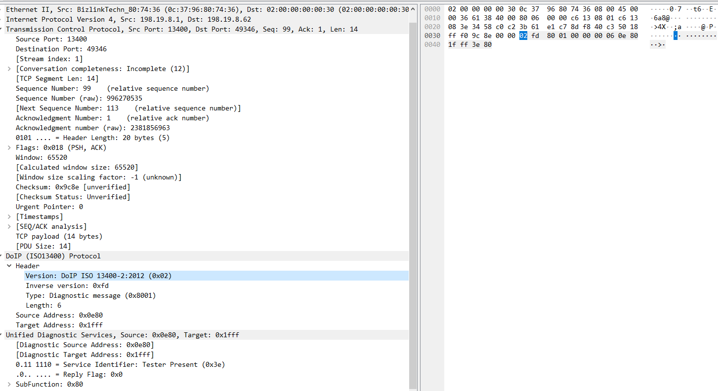
| 0x8001 | Diagnostic message | Container for the actual UDS (ISO 14229) diagnostic data payload | TCP | Both (Tester & Vehicle) | unicast |
| 0x8002 | Diagnostic message positive acknowledgement | Confirms the message was received and is correctly queued for routing (Does not imply UDS success) | TCP | DoIP entity | unicast |
| 0x8003 | Diagnostic message negative acknowledgement | Indicates a routing error (e.g. Target unreachable, Network unknown, Buffer too large) | TCP | DoIP entity | unicast |
A vehicle DoIP entity shall provide following information for identification: associated VIN, GID, and its EID, logical address.
GID: group identification number.
Acknowledgement message shall always be the response from Vehicle DoIP entity (external test equipment could implement the “Generic DoIP header negative acknowledge” for debugging purpose but it should be disable in production).

Vehicle DoIP entities process the received DoIP message and provide a generic negative response in case of received message has invalid header.

III.2 Core Functions
As previously described, both Edge, gateway and regular DoIP nodes should implement identical DoIP functionality. The only distinction is that internal vehicle nodes must route their communications to external test equipment through the Edge/gateway node, rather than a direct connection like the Edge node does.

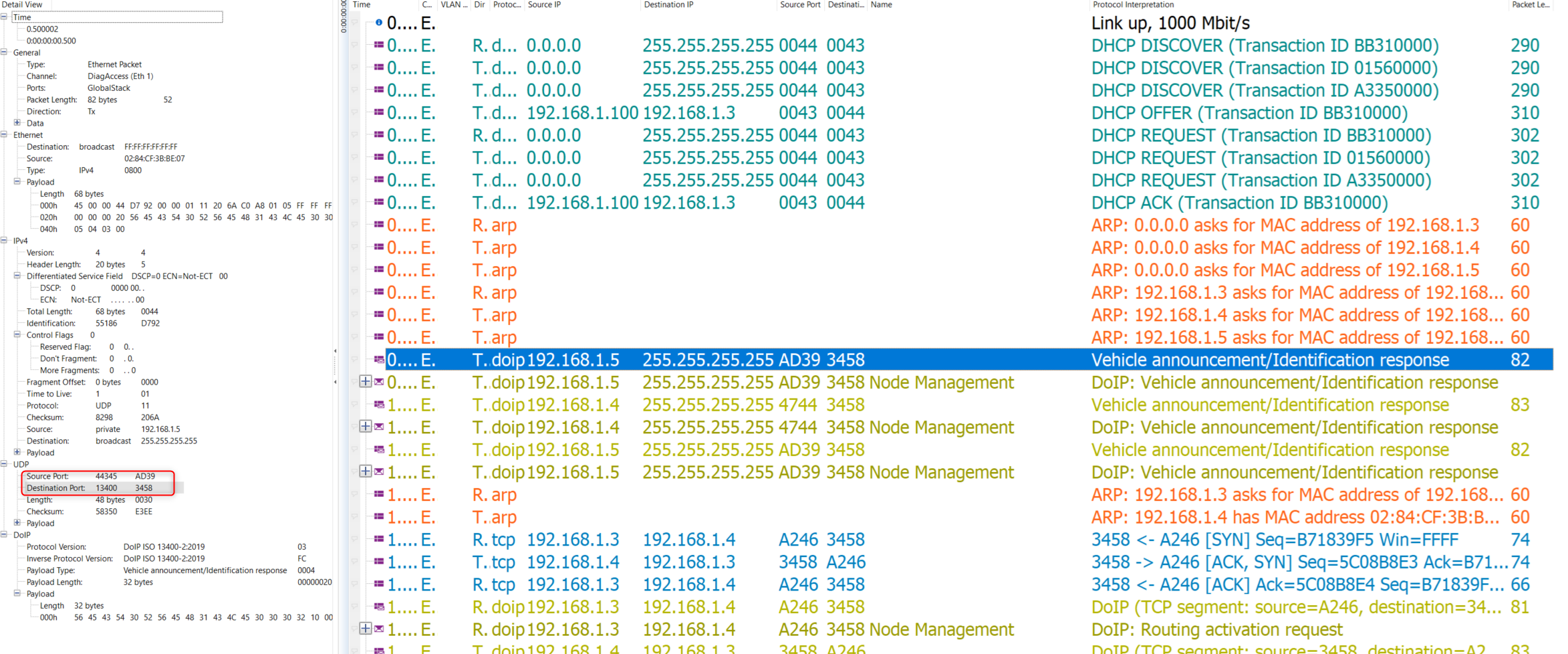
1. Vehicle Discovery and Identification broadcast via UDP Channel
The Vehicle discovery and identification is carry-out via UDP communication channel (broadcast or multicast address). As soon as the Ethernet communication is link-up and the IP addresses are assigned, to establish the DoIP communication, the following “Handshake” phase activities shall be performed:
- The external test equipment shall send in vehicle identification request
- The vehicle DoIP entities shall send out the vehicle identification announcement or vehicle identification response for incoming request.

Vehicle Identification fields:
- VIN (Vehicle Identification Number): unique number for each vehicle, comply with ISO3779 (e.g. WBAFR9C57CC123456)
- GID (Group Identifier): identify vehicle groups (fleet, model line)
- EID (Unique Identifier): unique identification of ECU, could be derived from MAC address (e.g. 00:1E:C0:2A:5B:48)
- Logical Address: DoIP entity logical address (e.g. 0x0E80=test equipment, 0x1D61=Brake System ECU)
- Further Action Required: 0x00 = No further action required, 0x10 = Routing activation required
- VIN/GID Sync Status: 0x00 = Vehicle DoIP entities VIN or GID are synchronized, 0x10 = not synchronized
Three different vehicle identification request types allow diagnostic testers to discover and target DoIP entities in flexible ways, depending on what information the tester already knows and the scenario (e.g. fleet management, workshop, production line or development,…).
- Generic Header Request (0x0001): “Who is out there?” (Broadcast to all).
- Request by EID (0x0002): “Is the ECU with EID(MAC address X) here?” (Targeted).
- Request by VIN (0x0003): “Is the vehicle with VIN Y here?” (Targeted).

From above example diagram, we can see the main steps:
- Ethernet interface link-up (Ethernet activation line to HIGH on OBD interface)
- IP assignment (DHCP or static or AutoIP)
- Vehicle DoIP entity broadcast their identity via Vehicle Identification Announcement
- External Test Equipment enquiry Vehicle Identification by request if they miss the vehicle announcement
⟹ After this phase, the External Test Equipment and Vehicle DoIP node should able to get information of their target (Identification, Logical Address, IP Address) and status for follow-up Routing Activation phase.
In case of internal vehicle ECUs in setup with direct connection to external tester, then the vehicle identification sequence is the same as DoIP Edge node show in above figure (either the ECU DoIP announcement reach tester first or tester send out the request to ECU DoIP instance).
Timing Requirements:
- Vehicle Identification Announcement message: on power-up or link-up, send announcement after initial delay A_DoIP_Announce_Wait ms (Random time: 0…500 ms).
- Vehicle Identification Response message: delay the response A_DoIP_Announce_Wait ms after receive the request (Random time: 0…500 ms).
- Vehicle Identification Announcement message: repeat A_DoIP_Announce_Num times (typically 3) with interval A_DoIP_Announce_Interval (500 ms).
Random A_DoIP_Announce_Wait value is to avoid UDP packet bursts on the network if many DoIP entities are connected to the same network
Comparison between Edge node and internal vehicle DoIP node in vehicle identification operation:
| Feature | DoIP Edge Node | Internal DoIP Node |
|---|---|---|
| Discovery Scope | Visible to External Network. | Invisible to External Network (unless directly connected). |
| Startup Behavior | Broadcasts Announcement (0x0004) to External UDP Port 13400. | Broadcasts Announcement only to Internal Network (if required). |
| Response to Tester | Responds to External Tester’s Request (0x0001). | Does not receive or respond to External Tester’s UDP broadcast. |
| Use Case | Primary point of contact for the vehicle. | Only acts as an Edge Node during direct connection (e.g. Bench testing). |
NOTE: If an Internal ECU is disconnected from the vehicle and connected directly to a tester (Peer-to-Peer), it effectively becomes an Edge Node for that session. It will perform the full Unsolicited Announcement sequence described above.
IPv4 vs IPv6 Differences in Vehicle Discovery:
- IPv4: Uses limited broadcast (255.255.255.255) or multicast for requests/announcements.
- IPv6: Uses link-local multicast (e.g. ff02::1) – no broadcast equivalent.
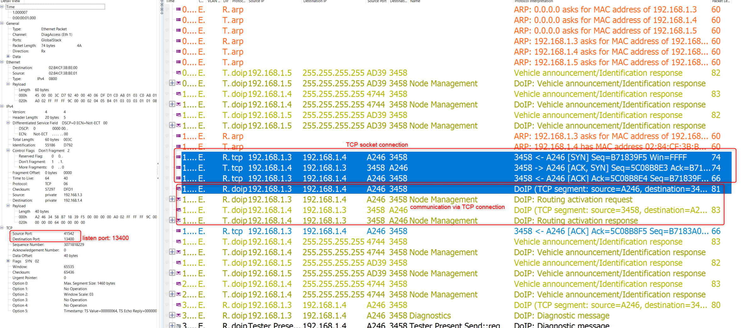
2. TCP Connection Establishment and Routing Activation
After external test equipment has identified the vehicle and its DoIP instances. To establish a DoIP diagnostic channel (logical link) to vehicle’s ECUs, dedicated TCP/IP connection between test equipment with the DoIP Edge node and between DoIP Edge node and internal vehicle ECU’s DoIP instances need to be created.

The main steps of this phase are:
1. Resolution of MAC addresses (ARP/NDP)
Before a TCP SYN packet can be sent, the Tester knows the Vehicle’s IP (from the previous UDP Vehicle Discovery phase) but needs the physical MAC address to frame the Ethernet packet.
- IPv4: Tester checks its local ARP Cache. If missing, it broadcasts an ARP Request: “Who has 192.168.1.10?”. Vehicle replies with its MAC.
- IPv6: Tester sends a Neighbor Solicitation (NS) to the solicited-node multicast address. Vehicle replies with a Neighbor Advertisement (NA) containing its MAC.
⟹ The Tester node can now construct Ethernet frames targeting specific DoIP Node.
2. Establishing the TCP connection via Three-Way Handshake
After the TCP Handshake is complete, the vehicle’s DoIP Entity change to socket initialized state, at this stage:
- UDS communication is not yet allowed (i.e. Diagnostic Messages 0x8XXX).
- Allowed DoIP message: Routing Activation (0x0005), Alive Check (0x0007).

A DoIP socket instance is identified by IP source/destination address pair, port and registered Tester’s Logical Address(Source Address) on that TCP/IP socket
3. DoIP “Log-in” with Routing Activation
This is the DoIP-specific “Log-in” process. The Tester must explicitly ask for permission to send diagnostics.

Routing Activation Request:
| Routing Activation Type | Description |
|---|---|
| 0x00 | Default |
| 0x01 | WWH-OBD |
| 0x02 | to 0xDF ISO/SAE reserved |
| 0xE0 | Central security |
| 0xE1 | to 0xFF Available for additional OEM-specific use |
Routing Activation Response:
| Routing Activation response code value | Description | Required Action |
|---|---|---|
| 0x00 | Routing activation denied due to unknown source address | Do not activate routing and close this TCP_DATA socket |
| 0x01 | Routing activation denied because all concurrently supported TCP_DATA sockets are registered and active | Do not activate routing and close this TCP_DATA socket |
| 0x02 | Routing activation denied because an SA different from the table connection entry was received on the already activated TCP_DATA socket | Do not activate routing and close this TCP_DATA socket |
| 0x03 | Routing activation denied because the SA is already registered and active on a different TCP_DATA socket | Do not activate routing and close this TCP_DATA socket |
| 0x04 | Routing activation denied due to missing authentication | Do not activate routing and register |
| 0x05 | Routing activation denied due to rejected confirmation | Do not activate routing and close this TCP_DATA socket |
| 0x06 | Routing activation denied due to unsupported routing activation type | Do not activate routing and close this TCP_DATA socket |
| 0x07 – 0x0F | Reserved by this part of ISO 13400 | — |
| 0x10 | Routing successfully activated | Activate routing and register SA on this TCP_DATA socket |
| 0x11 | Routing will be activated; confirmation required | Only activate routing after confirmation from within the vehicle |
| 0x12 – 0xDF | Reserved by this part of ISO 13400 | — |
| 0xE0 – 0xFE | Vehicle-manufacturer specific | — |
| 0xFF | Reserved by this part of ISO 13400 | — |
Vehicle Validation Logic:
From above routing activation response code, we can se the DoIP Node shall checks:
- Is the Source Address known and valid(i.e. registered for current socket)?
- Is the requested routing activation on the current socket valid?
- Is socket resource available?
NOTE: When checking whether socket resource is available, the DoIP node send out the “Alive Check” message to confirm if the socket connection is still in use or not.
- Does this Tester require special authentication? (OEM specific e.g. completion of TLS handshake for secure DoIP session over TCP connection or additional authentication sequence for DoIP access)
- Does additional confirmation is required for current connected tester? (OEM specific .e.g user confirmation to activate the DoIP session in vehicle MHU)

⟹ Routing Activation success then DoIP socket connection moves to Routing Activated state, and Tester can send UDS commands (0x8XXX).
3. Diagnostic Message Transport
After routing activation stage, the UDS application data exchange can be carry-out.
- The UDS application data(service request/response) shall be sent via DoIP message type of 0x8001.
- When receive “Diagnostic message”, DoIP node shall perform validation of incoming diagnostic message and provide an initial DoIP response. If any of the error in NACK table occur, DoIP node send back 0x8003 negative response with corresponding NACK code, else a 0x8002 positive response along with ACK will be send back.
- Valid diagnostic message’s “UDS Data” shall be route to UDS application/gateway layer for further process.

| Diagnostic message positive response code | Description | Support |
|---|---|---|
| 0x00 | Routing confirmation acknowledge (ACK) message indicating that the diagnostic message was correctly received, processed and put into the transmission buffer of the destination network. | mandatory |
| 0x01…0xFF | Reserved by this part of ISO 13400. | — |
| Diagnostic message negative response code | Description | Support |
|---|---|---|
| 0x00…0x01 | Reserved by this part of ISO 13400 | — |
| 0x02 | Invalid source address | mandatory |
| 0x03 | Unknown target address | mandatory |
| 0x04 | Diagnostic message too large | mandatory |
| 0x05 | Out of memory | mandatory |
| 0x06 | Target unreachable | optional |
| 0x07 | Unknown network | optional |
| 0x08 | Transport protocol error | optional |
| 0x09…0xFF | Reserved by this part of ISO 13400 | — |

4. Session Handling and Reset Behavior
To ensure a stable diagnostic session—especially during long operations like ECU flashing, DoIP specification also specify some other operations and corresponding message type for monitoring socket connection aliveness(Alive Check), query node capabilities(Entity Status), and verify vehicle readiness(Power Mode).

| Payload | Message Name | Protocol | Sender | Purpose |
|---|---|---|---|---|
| 0x0007 | Alive Check Request | TCP | Vehicle | Are you still there? |
| 0x0008 | Alive Check Response | TCP | Tester | Yes, I am connected response or Heart beat signal |
| 0x4001 | Entity Status Request | UDP | Tester | Query buffer size and socket capacity. |
| 0x4002 | Entity Status Response | UDP | Vehicle | Reports specific node capabilities. |
| 0x4003 | Power Mode Request | UDP | Tester | Is the vehicle ready for diagnostics? |
| 0x4004 | Power Mode Response | UDP | Vehicle | Reports Ready/Not Ready state. |
4.1. DoIP TCP_DATA Session Maintenance: The Alive Check Mechanism
As mention in section II about the TCP connection, if DoIP node support <n> concurrent session it should provide <n+1> TCP sockets so that it still able to listen for new connection request and then check existed one whether they still available or not to release resource and provide for the new one.
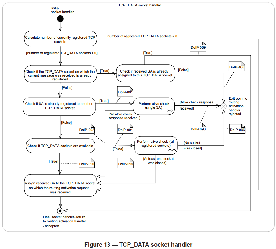
The alive check shall be done by DoIP vehicle node when receive routing activation request, to look for idle TCP_DATA socket and reuse.
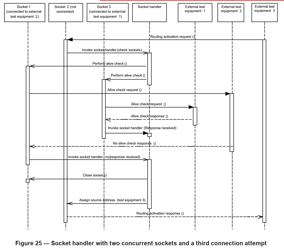
Scenario Breakdown (Based on the diagram above):
Context: The Vehicle DoIP node supports 2 concurrent diagnostic sessions but maintains 3 TCP sockets total (N+1).
- Sockets 1 and 3 are currently connected with active sessions. The limit (2) is reached.
- Socket 2 is free and listening for incoming connections.
- A new Tester (Tester 3) connects to Socket 2 and sends a Routing Activation Request.
- To determine if it can accept this new tester, the DoIP node performs an Alive Check on the existing connections (Sockets 1 and 3).
- Socket 1 fails to respond (e.g., the previous tester crashed or disconnected without a FIN). The DoIP node closes Socket 1 to free up the resource.
- The DoIP node now accepts the connection on Socket 2. Sockets 2 and 3 are now active. Socket 1 becomes the new listener.
7.(Alternative): If both Socket 1 and Socket 3 had responded to the Alive Check, the node would be at full capacity. The Routing Activation on Socket 2 would be declined (typically with code 0x03 - Socket Registered/Active).
⟹ When a connection is no longer required, the External Test Equipment should always close it gracefully using standard TCP FIN mechanisms. If the connection is not closed properly (e.g. cable pull), the DoIP entity will eventually free the resource either through the Alive Check process described above or via a general Inactivity Timer.
4.2. Vehicle and DoIP Entity Status Inspection
Before initiating a full diagnostic session, it is often necessary to inspect the vehicle’s capabilities using UDP messages. This helps prevent protocol errors during operation.
Querying Capabilities (0x4001 / 0x4002) Before starting memory-intensive operations (like flashing), the Tester sends a DoIP Entity Status Request (0x4001). The Edge Node responds (0x4002) with critical limits:
- Max Data Size: The maximum size of a DoIP message the node can process (e.g., 32KB). If the Tester exceeds this, the node will reject the packet with NACK code
0x04(Message Too Large). - Max TCP Sockets: The maximum number of concurrent testers supported.
Ethernet communication requires significant power. A vehicle’s network interface might be online (responding to Pings) while the rest of the ECU network is in a low-power sleep mode.
Checking Readiness (0x4003 / 0x4004) The Tester should poll the Diagnostic Power Mode Info Request (0x4003) after waking the vehicle.
- Response
0x00(Not Ready): The Tester should wait. - Response
0x01(Ready): The vehicle is fully awake, and the Tester can proceed to open a TCP connection and perform Routing Activation.
4.3. Session Termination
A DoIP session is terminated in one of the following ways:
- Graceful Disconnect (Standard): The Tester sends a TCP FIN packet. The Edge Node acknowledges, closes the socket, and resets the routing activation state.
- Protocol Violation (Error): If the Tester violates the state machine (e.g. sending UDS data before Routing Activation or sending malformed headers), the Edge Node sends a Negative Acknowledge and immediately resets (closes) the TCP socket.
- Timeout Reset (Idle): If a socket remains idle beyond the defined limit and fails the Alive Check (no response from Tester), the Edge Node performs a local reset to free the resource.
5. Ethernet Interface Activation Line
Before any TCP/IP communication can occur, the physical connection must be established. Unlike standard consumer Ethernet (which is “always on” or wakes on link pulses), automotive Ethernet PHYs (Physical Layer Transceivers) are typically powered down when the vehicle is idle to prevent battery drain.
The Activation Mechanism: ISO 13400-3 specifies a dedicated Activation Line on the diagnostic connector (OBD-II).
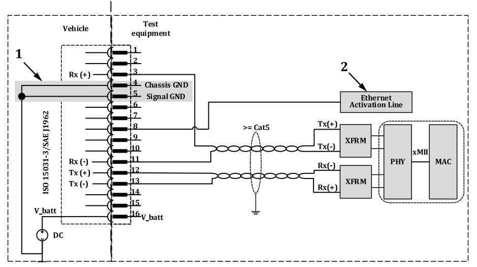
- Sleep State: By default, the DoIP Edge Node keeps its Ethernet PHY in a power-down state.
- Activation: The External Test Equipment asserts a high voltage level (typically V_bat or >5V) on the Activation Pin.
- Wake-up Sequence:
- The DoIP Edge Node detects the voltage Edge.
- It wakes up its CPU and powers on the Ethernet PHY.
- Link Training: The PHYs perform auto-negotiation (100BASE-TX) or link training (100BASE-T1/1000BASE-T1).
- IP Configuration: Once the link is stable, the DHCP negotiation begins.
Note: If the Activation Line is de-asserted (voltage drops) during a session, the DoIP Edge Node interprets this as a disconnect event and will immediately shut down the Ethernet PHY to save power, terminating all active TCP sockets.
Summary:
In practical automotive development, most of DoIP implementation complexity reside in edge nodes. These include functionalities such as tester handling, processing diagnostics from multiple vehicle diagnostic interfaces (e.g. OBD and Wi-Fi), UDS firewall, gateway routing, and overall connection management. In contrast, other in-vehicle DoIP nodes can typically rely on a standardized DoIP software stack, which only needs configuration or minor adaptation to meet OEM-specific functional and performance requirements.