ISO26262 - Fault Tolerance Time Interval(FTTI)
This blog shall provide an overview, analysis and possible approach on System Fault Tolerance Time Interval(FTTI), which is an important attribute that need to be addressed when design safety system.
I. Terminology
Term and definition that related to FTTI.
vehicle function: behaviour of the vehicle, which is implemented/relized by one or more vehicle items, that is observable by the customer.
item: system or combination of systems, that implements a function or part of a function at the vehicle level.
system: set of components or subsystems that relates at least a sensor, a controller and an actuator with one another (The related sensor or actuator can be included in the system, or can be external to the system).
element: system, components (hardware or software), hardware parts, or software units.
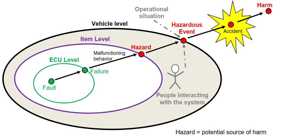
hazard: potential source of harm caused by malfunctioning behaviour of the item.
hazardous event: combination of a hazard and an operational situation.
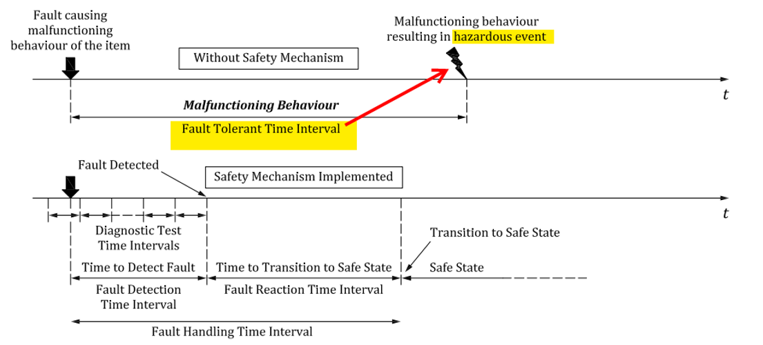
FTTI: minimum time-span from the occurrence of a fault in an item to a possible occurrence of a hazardous event, if the safety mechanisms are not activated(or no safety mechanism).
- minimum time-span is to be evaluated over all hazardous events.
- derived from hazard.
- define at item level (SGs, FSCs) as a design constraint of vehicle functions.
FHTI: sum of fault detection time interval and the fault reaction time interval
- time-span from existence of element’s faults to safe state achieve by the system (safety mechanism execute successful)
- smaller than top level FTTI, the smaller the better (exact margin is to be decided by system designer and system performance characteristics)
- define at element level (system, software, hardware)
FDTI: time-span from the occurrence of a fault to its detection.
FRTI: time-span from the detection of a fault to reaching a safe state.
FHTI(FDTI + FDTI): to be apply as design constraint for system level and lower level design/implementation.
II. Concept
II.1 Analyze on FTTI characteristics
Analyze of operational hazard & fault manifestation process:
So we can see, in a vehicle hazardous event might not existed immediately upon some component fault, it shall take time for that fault to propagate through the system before causing failure effect to the vehicle functions (malfunction manifestation time).
And in some cases, when vehicle function failure exist(hazard exist), the hazardous event does not become available immediately, it might take some specific operational situation (hazard manifestation time).
The malfunction causing hazardous event can be categorize into:
- Effects is perceptible at once (failure = immediately trigger).
Ex: electrical motor burn/blow-up due to overheat, short-circuit lead to vehicle immediately loss of power propulsion during driving, hazardous event lead to accident. - Effects is perceptible in special situations only (situation trigger).
Ex: onboard charger module has insulation failure, causing current leakage into vehicle chassis, body with no detection and warning. Upon user perform charging and touch the vehicle part, lead to shock accident.
II.2 Concept level(vehicle) approach on define FTTI value for SGs, FSC/FSR base on Item Definition and HARA
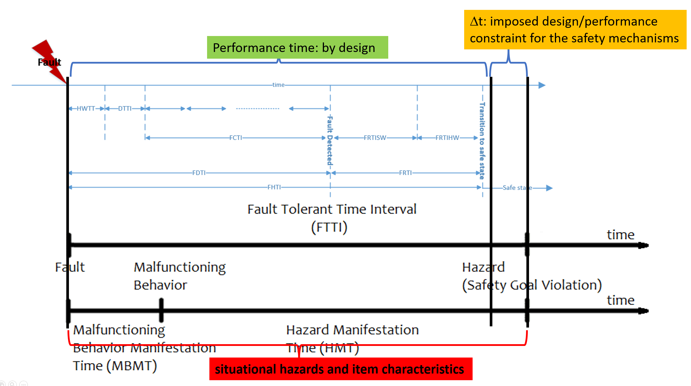
From the analysis above, we can define:
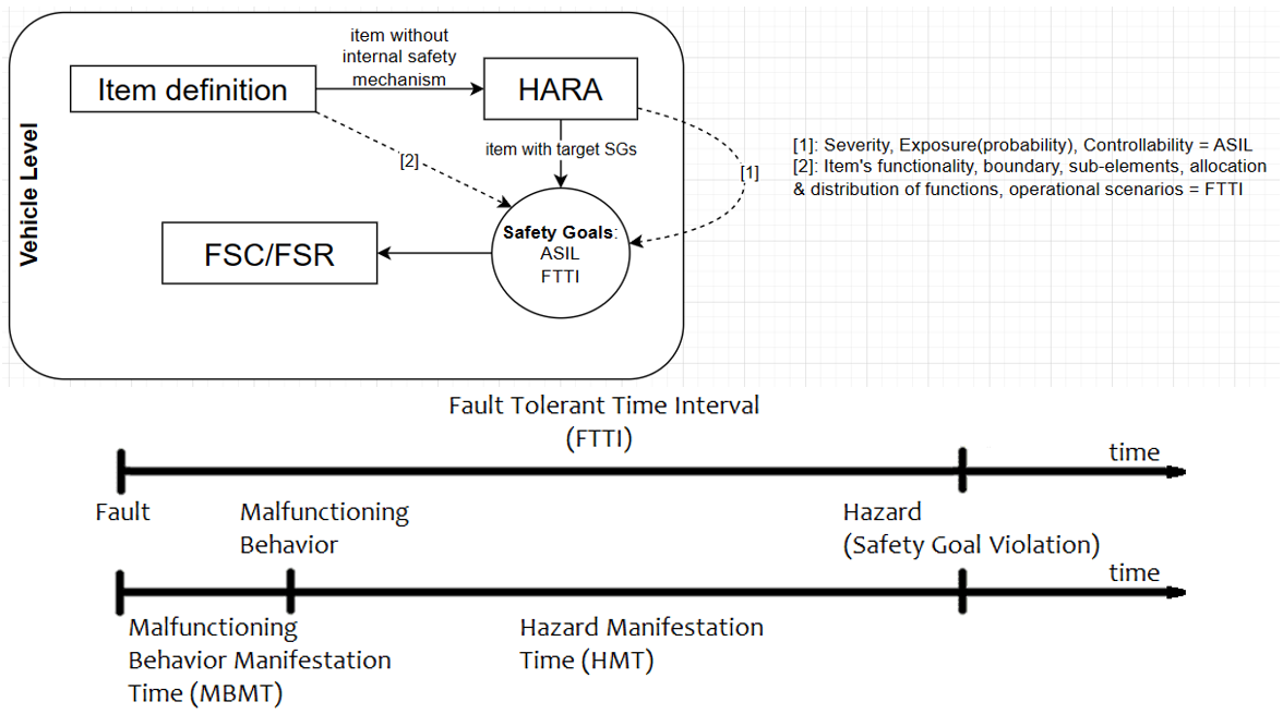 Malfunctioning Behavious Manifestation Time(MBMT): time it takes for a failure to manifest itself to vehicle level is entirely dependent upon how the failing component is used in the target function (i.e. from fault to failure on vehicle function).
Ex: fault in displayed vehicle speed = vehicle speed sensor(sensing, signal-transmission) -> IBD(processing, transmission) -> Gateway ECU(processing, transmission) -> MHU(processing, rendering) -> MDU(display)
So we can conclude that MBMT is a result of vehicle architecture and item’s functional design.
Hazard Manifestation Time(HMT): from the point of the Malfunctioning Behavior existence to a specific operational scenario/action that cause hazardous event to exist.
Ex: A failure in vehicle turn signal may not result in a hazardous event until user change direction, driving lane without turn light indicator to signal other vehicles.
HMT in the other hand is influenced entirely by the operational scenario and the Malfunctioning Behavior(hazard) being considered.
FTTI = MBMT + HMT (forms the constraint, imposes on the design for items/vehicle function)
Example: single point fault that lead to failure at eCockpit system 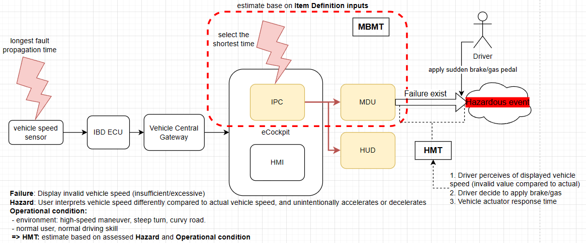 Analysis for the invalid display vehicle speed hazard case above:
Fault occur in vehicle speed calculation in IPC component, MDU screen 60Hz ⟹ MBMT ~ 0.02s
From the point of malfunction IPC exist to where driver decide to interact with vehicle by apply break pedal.
That’s depended on driver perception of invalid vehicle speed in display Instrument Panel Cluster or Head-up Display. Let’s say normal scan time is 0.5s and driver decide to take reaction by apply sudden brake(operational scenario/action), which cause hazardous event ⟹ HMT ~ 0.5s
⟹ FTTI = HMT(0.5s) + MBMT(0.02s) = 520ms
Maximum braking depends on vehicle weight and tire traction, width and diameter ⟹ vehicle specific deceleration rate ⟹ rear end collision (less controllable).
Maximum vehicle acceleration depends on tires and horsepower ⟹ vehicle specific acceleration rate ⟹ front end collision (driver in more active position).
In this case rear end collision is likely to occur more and has higher degree of hazardous.
With normal distance between vehicle – hazardous event, collision accident assessment shall take into account of: distance between 2 vehicle, time, vehicle speed different, deceleration/acceleration
Rear end: distance 10m, both vehicle at same speed(current_speed)
- Vehicle(A) slow down: v(current_speed)t - 0.5a*t^2
- Vehicle(B driving after vehicle A) at constant speed: v(current_speed)*t
⟹ Deceleration with max value of vehicle(due to driver panic or low driving skill) ⟹ a = 4.512 m/s^2 ⟹ 10m distance to rear end collision = sqrt(10/(0.5 * 4.512)) = 2.1s.
Accident could occur after 2.1s from the point of hazardous event
So the FTTI = 520ms value should be a reasonable value considering the current assessed hazard
4.512 m/sec2 (0.47 g’s) as the maximum deceleration that is safe for the average driver to maintain control, good to excellent tires, dry surface
Summary on analysis and approach to define FTTI:
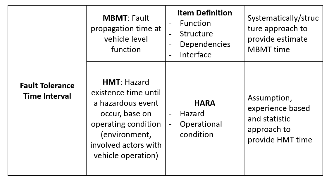 MBMT: rough calculation from inputs of Item Definition ⟹ a more systematically/structure approach by scanning through item function behaviors, item boundary, identify possible single point fault with shortest propagation time.
HMT: more experience base and statistic approach ⟹ analyze operating condition, type of hazard, user controllability and probability of exposure.
III. System
III.1 Fault propagation
A failure at one architectural level (e.g. ECU level) can become a fault at an upper architectural level (e.g. item level) as shown hereafter:
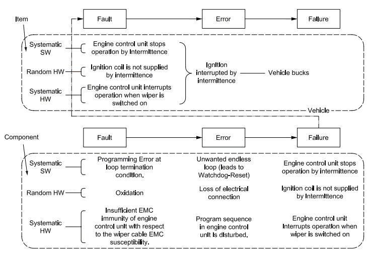 Fault propagation: components fault(Single Point Fault-SPF, Multiple Point Fault-MPF) create failure of component, which create fault(directly or in combination with other component failure) at vehicle function(cascading, common) and result into failure of vehicle (causing harm).
III.2 Time evaluation: define FDTI and FRTI base on design constraint
 After receive FTTI value from the concept level, system designer(ECU level) shall responsible to derive the FHTI(FDTI + FRTI) value, which has to be smaller than FTTI. And smaller to what margin(Δt or %) is up to the designer. The bigger margin value the better.