GB/T 27930 China Charging Communication Standard Overview
This blog shall take a look into the GB/T(China National Standard) charging standard, and focus mostly on the communication and charging sequence of DC charging system.
Similar to the Society of Automotive Engineers(SAE), the International Electro-technical Commission(IEC), or the International Standards Organization(ISO) which provide standard specification to address general, physical, and signaling requirements for electric vehicle charging system.
GB/T set of standards also address above charging functionalities for both AC and DC fast charging infrastructure used in China:
- GB/T 18487 provides general requirements for conductive charging systems (both AC & DC) ⇔ IEC 61851.
- GB/T 20234 provides physical requirements for connectors and interfaces ⇔ IEC 62196 and SAE J1772.
- GB/T 27930 provides communication requirements in case of DC charging ⇔ ISO 15118 and SAE J1772.
GB/T 27930(Communication Protocol between Off-board Conductive Charger and Battery Management System of Electric Vehicle - DC charging) use J1939:2006 specification for the underlying transportation layer operation. Communication between EV and Charging Station shall be done via CAN 2.0B protocol and the CAN network shall only contain 2 nodes (EV and CS).
More information on GBT charging sequence can be found in GB/T 18487.1 Appendix B. DC Charging Control Pilot Circuit and Control Principle.
NOTE: Charging Station(CS) or Charger: these term shall be used interchangeably in this blog to address the whole Electric Vehicle Charging Station system (all physical, electrical components stand between Electrical Grid and Electrical Vehicle)
In IEC 61851 specification: GB/T DC type of Charging System is addressed as ChargingSystem B
This blog will inspect primarily the GB/T DC charging system and related communication protocol, for GB/T AC charging please refer to [TBD] since it similar to IEC 61851.1 AC charging system.
I. Physical Interface
On the physical interface level, the conductive charging connection between EV and CS include:
- conductive power transfer line(AC or DC, earth protective)
- communication signal lines (proximity, general purpose physical signals, digital communication signal).
For the AC charging system in GB/T, its operation and communication scheme is the same as IEC 61851-1 (basic signalling via Control Pilot line: PWM duty cycle and voltage level to signal available output power and charge operation status)
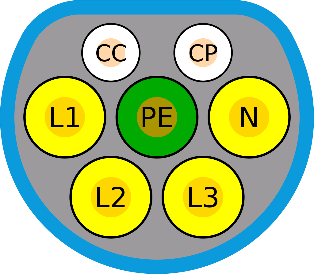
CC: proximity line
CP: control pilot line(basic signalling with PWM and voltage level control)
L1,L2,L3: AC power line (phase1-3), if charging station only support 1 phase AC then L1 shall be used.
N: neutral
PE: protective earth
For the DC charging system in GB/T, its operation and communication shall be carry-out via general physical signals and CAN communication bus, which is complied with ISO11898, and the baudrate of 250 kbits/s.
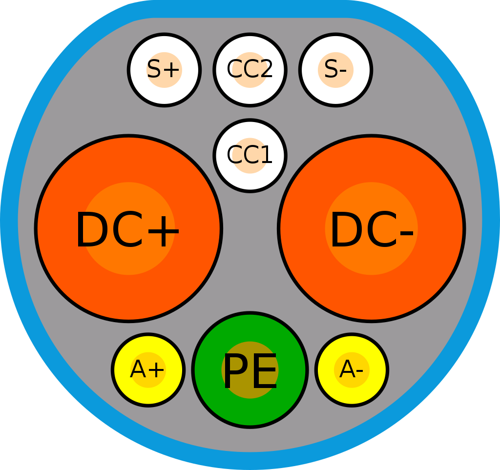
S+, S-: CAN-H and CAN-L signal line
CC1, CC2: charging control(charging check point) or connection confirm signal
DC+, DC-: DC power line
PE : protective earth
A+, A-: auxiliary power supply, 12V low voltage to supply the charging circuit on Vehicle side
II. Charging System
An example of DC charging assembly components on both EV and Charging Station side.
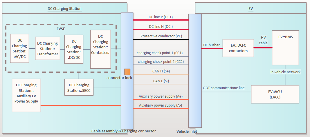
EVSE: Electric Vehicle Supply Equipment, normally it will be the power electronic conversion circuitry, safety monitoring devices, and actuator components(grid side, vehicle side contactors),…
SECC: Supply Equipment Communication Controller, handle the charging process control and communication with other actors in a EV charging infrastructure such as: EV, Charging Station Management System (CSMS), EV user.
DCFC: DC Fast-Charge Contactors, vehicle side High Voltage(HV) contactors, use to open or close the HV power transmission from Vehicle side.
BMS: Battery Management System, control the actuator on HV DC busbar, monitor and regulated charging of HV Battery.
VCU: Vehicle Control Unit(EV Communication Control), handle the charging process of the EV and communication with the Charging Station(SECC).
So you can see the communication via charging cable(interface) are carry-out by SECC and EVCC component(generally shall be allocated to EV’s VCU or an generic component that handle vehicle overall charging communication feature), other ECUs(BMS or other power electronic ECUs) shall responsible for actuator operating(DCFC contactors), monitoring and reporting the status(voltage, current, etc.) back to the communication and charging control unit.
III. Data Link Layer
- For the CAN frame format: CAN 2.0B extended 29bits identifier is used, and PDU bit allocation comply with SAE J1939-21:2006.
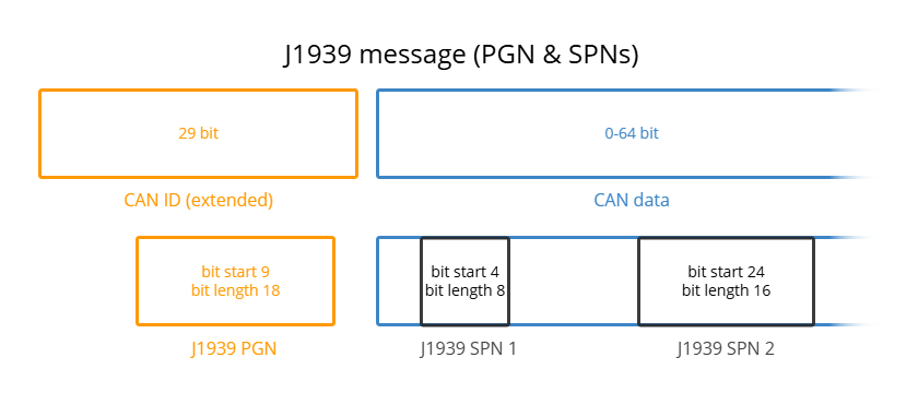
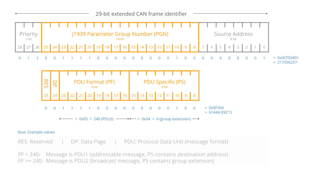
PGN: Parameter Group Number, 18-bit value which is used as a unique identifier of one parameter group, including reserved bit(R), data page(DP), PDU format field (8-bit)(PF) and PDU specific field (8-bit)(PS).
NOTE: The PGN definition in GB/T 27930 is slightly differ from J1939.
PGN hasbyte 0 and 2 = 0x00,e.g. PF = 0x01 ⟶ PGN = 0x000100, PF = 0x08 ⟶ PGN = 0x000800P: priority, set from the highest 0 to the lowest 7
R: reserved bit or extended data page, set as 0
DP: data page, used to select the auxiliary page for the description of parameter group, set as 0
PF: define the used PDU format and parameter group number, in GB/T 27930 PDU1 format is used ⟹PS is used to store destination address(DA)
PS: PDU specific, used to store the destination address
SPN: Suspect Parameter Number, a logic ID which is allocated to each parameter by Application Layer.
| Device | Address |
|---|---|
| Charger | 86 (0x56) |
| BMS | 244 (0xF4) |
Payload data: transmission of 9~1785 byte data between BMS and charger shall use the J1939 transport protocol function.
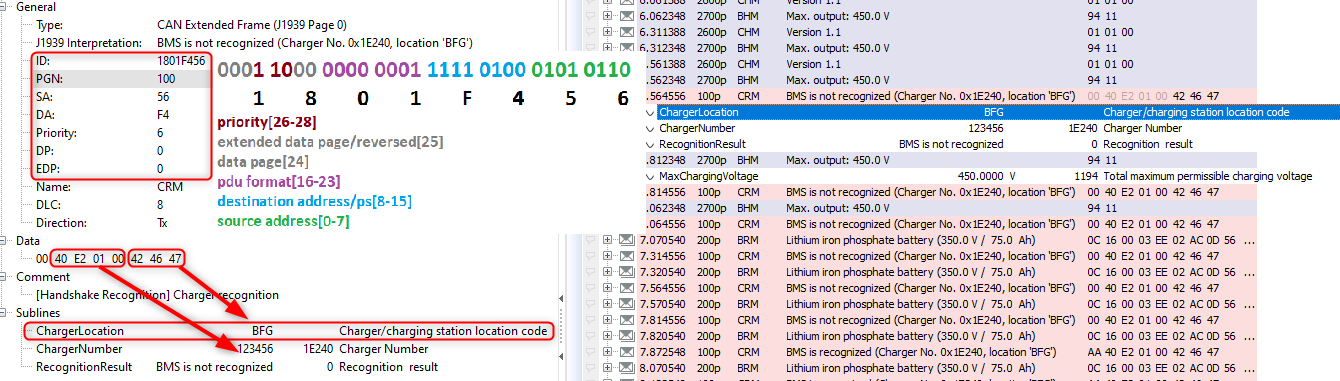
As you can see, the CRM frame(from Charger) has PDU Format = 0x01 -> PGN = 0x100. Fixed SA = 0x56, DA = 0xF4
The application parameters(SPN) are stored CAN frame data field with motorola byte order.
IV. Application Layer
The normal charging process of GB/T standard is divided into 5 stages and fault handling operation in case of errors occur during charging process:

- initial physical connection and auxiliary power supply: this phase revolving around
- detection of physical connection between vehicle inlet and charging gun connector via CC1, CC2 signals and
- providing auxiliary low voltage power supply to vehicle side(optional, EV could use this auxiliary power supply from EVSE or not).
- charging handshake: sending protocol and system specific identifier(both EV and CS) handshake data such as
- initiation: protocol version, maximum HV battery voltage
- recognition: BMS/vehicle and charger recognition information(battery type, manufacturer, VIN, charger location code,…). After verifying identification of other parties and agree on used protocol version. EV and CS move to the next stage of set-up charging session parameter.
- charging parameter configuration:
- capabilities and current status of EV Battery and Charger
- EV and Charger ready status
- charging loop/energy transfer loop:
- BMS charging demand, current state.
- Charger status
- end of charging:
- BMS end of charge status
- error handling (monitoring and fault reaction during charging process): during the charging process, different faults could occur and there will be corresponding fault reaction operation:
- permanent fault and emergency shutdown.
- recoverable fault and required shutdown and start new charging cycle by unplug and re-plug charging gun.
- recoverable fault and suspend charging and try restart communication when fault is healed.
GB/T 27930 message list
| Name | ID | PGN | Source | Destination | DLC [Byte] | Tx Method | Cycle Time | Transmitter | Comment | Priority | TpJ1939VarDlc |
|---|---|---|---|---|---|---|---|---|---|---|---|
| BHM | 0x182756F4 | 0x2700 | 0xF4 | 0x56 | 2 | cyclic | 250 | BMS | [Handshake Initiation] Vehicle handshake | 6 | No |
| BRM | 0x1C0256F4 | 0x200 | 0xF4 | 0x56 | 49 | cyclic | 250 | BMS | [Handshake Recognition] BMS and vehicle recognition message | 7 | Yes |
| BCP | 0x1C0656F4 | 0x600 | 0xF4 | 0x56 | 13 | cyclic | 500 | BMS | [Parameter Configuration] Charging parameters of power storage battery | 7 | No |
| BRO | 0x100956F4 | 0x900 | 0xF4 | 0x56 | 1 | cyclic | 250 | BMS | [Parameter Configuration] Battery charging ready state | 4 | No |
| BCL | 0x181056F4 | 0x1000 | 0xF4 | 0x56 | 5 | cyclic | 50 | BMS | [Charging] Battery charging demand | 6 | No |
| BCS | 0x1C1156F4 | 0x1100 | 0xF4 | 0x56 | 9 | cyclic | 250 | BMS | [Charging] Overall battery charging status | 7 | No |
| BSM | 0x181356F4 | 0x1300 | 0xF4 | 0x56 | 7 | cyclic | 250 | BMS | [Charging] Power storage battery status information | 6 | No |
| BMT | 0x1C1656F4 | 0x1600 | 0xF4 | 0x56 | 128 | cyclic | 10000 | BMS | [Charging] Temperature of power storage battery [OPTIONAL] | 7 | Yes |
| BMV | 0x1C1556F4 | 0x1500 | 0xF4 | 0x56 | 512 | cyclic | 10000 | BMS | [Charging] Single power storage battery voltage [OPTIONAL] | 7 | Yes |
| BSP | 0x1C1756F4 | 0x1700 | 0xF4 | 0x56 | 16 | cyclic | 10000 | BMS | [Charging] Reserved message of power storage battery [OPTIONAL] | 7 | Yes |
| BST | 0x101956F4 | 0x1900 | 0xF4 | 0x56 | 4 | cyclic | 10 | BMS | [Charging] BMS suspending charging | 4 | No |
| BSD | 0x181C56F4 | 0x1C00 | 0xF4 | 0x56 | 7 | cyclic | 250 | BMS | [EndOfCharging] BMS statistical data | 6 | No |
| BEM | 0x81E56F4 | 0x1E00 | 0xF4 | 0x56 | 4 | cyclic | 250 | BMS | [Error] BMS’s error message | 2 | No |
| CHM | 0x1826F456 | 0x2600 | 0x56 | 0xF4 | 3 | cyclic | 250 | Charger | [Handshake Initiation] Charger handshake | 6 | No |
| CRM | 0x1801F456 | 0x100 | 0x56 | 0xF4 | 8 | cyclic | 250 | Charger | [Handshake Recognition] Charger recognition | 6 | No |
| CML | 0x1808F456 | 0x800 | 0x56 | 0xF4 | 8 | cyclic | 250 | Charger | [Parameter Configuration] Charger’s maximum output | 6 | No |
| CRO | 0x100AF456 | 0xA00 | 0x56 | 0xF4 | 1 | cyclic | 250 | Charger | [Parameter Configuration] Charger output ready state | 4 | No |
| CCS | 0x1812F456 | 0x1200 | 0x56 | 0xF4 | 8 | cyclic | 50 | Charger | [Charging] Charger’s charging status | 6 | No |
| CST | 0x101AF456 | 0x1A00 | 0x56 | 0xF4 | 4 | cyclic | 10 | Charger | [Charging] Charger suspending charging | 4 | No |
| CSD | 0x181DF456 | 0x1D00 | 0x56 | 0xF4 | 8 | cyclic | 250 | Charger | [EndOfCharging] Charger’s statistical data | 6 | No |
| CEM | 0x81FF456 | 0x1F00 | 0x56 | 0xF4 | 4 | cyclic | 250 | Charger | [Error] Charger’s error message | 2 | No |
| CTS | 0x1807F456 | 0x700 | 0x56 | 0xF4 | 7 | cyclic | 500 | Charger | [Parameter Configuration] Charger send-time synchronization information 1. byte: second; 2. byte: minute; 3. byte: hour; 4. byte: day; 5. byte: month; 6. and 7. bytes: year. All values as compressed BCD code. | 6 | No |
| DM1 | 0x1820FEFE | 0x2000 | - | - | 20 | - | 0 | - | Current fault code | 6 | Yes |
| DM2 | 0x1821FEFE | 0x2100 | - | - | 20 | - | 0 | - | Historic fault code | 6 | Yes |
| DM3 | 0x1822FEFE | 0x2200 | - | - | 2 | - | 0 | - | Diagnose ready Attention: Incomplete signal set! | 6 | No |
| DM4 | 0x1823FEFE | 0x2300 | - | - | 0 | - | 0 | - | Clear/reset of current fault code | 6 | No |
| DM5 | 0x1824FEFE | 0x2400 | - | - | 0 | - | 0 | - | Clear/reset of historic fault code | 6 | No |
| DM6 | 0x1825FEFE | 0x2500 | - | - | 1785 | - | 0 | - | “Freeze frame parameter Attention: Incomplete signal set!” | 6 | Yes |
| RQST | 0x18EAFEFE | 0xEA00 | - | - | 3 | - | 0 | - | Request: This message type, identified by the PGN, provides the capability to request information globally or from a specific destination. | 6 | No |
| ACKM | 0x18E8FEFE | 0xE800 | - | - | 8 | - | 0 | - | Acknowledgment Message: The Acknowledgment PG is used to provide a handshake mechanism between transmitting and receiving devices. | 6 | No |
| TPCMxx | 0x18ECFEFE | 0xEC00 | - | - | 8 | - | 0 | - | Transport Protocol - Connection Mgmt: Used for the transfer of Parameter Groups that have 9 or more bytes of data. | 6 | No |
| TPDT | 0x18ECFEFE | 0xEB00 | - | - | 8 | - | 0 | - | Transport Protocol - Data Transfer: Used for the transfer of data associated with Parameter Groups that have more than 8 bytes of data. | 6 | No |
Protocol sequence
The charging control operation shall be managed by BMS/Vehicle side. The application message transmission during charging process are both event-driven and periodically.
The general timeout(does not receive or received incorrect message) of application message is all 5s unless otherwise specified, for the general communication message timeout, EV or CS shall send timeout error status message to other parties and enter corresponding fault handing reaction.