EGAS Architecture Concept
In automotive domain, if you have chances to work with ICE engine management application, then probably you have heard about EGAS(electronic gas pedal) concept. What is it and how it is related to safety monitoring and management functions?
In this post, we will go through the overview of EGAS concept, there will be deviation because my experience with applying EGAS concept is not with an ICE engine management ECU. But in the end, I think it will be the same in term of target and core principles for any kind of project. For the specification of EGAS, you can search and find it on the internet.
I. Introduction
Drive-by-Wire-Systems are now state-of-the-art technology for control gasoline and diesel engines. The high conditions on these systems and the integration into networked vehicle systems requires a closely monitoring of their functionalities.
A group of German automotive manufacturers(VDA) have created the EGAS working group, with target of standardize the monitoring concept for their engine control system. Below image show the main points about EGAS Concept. 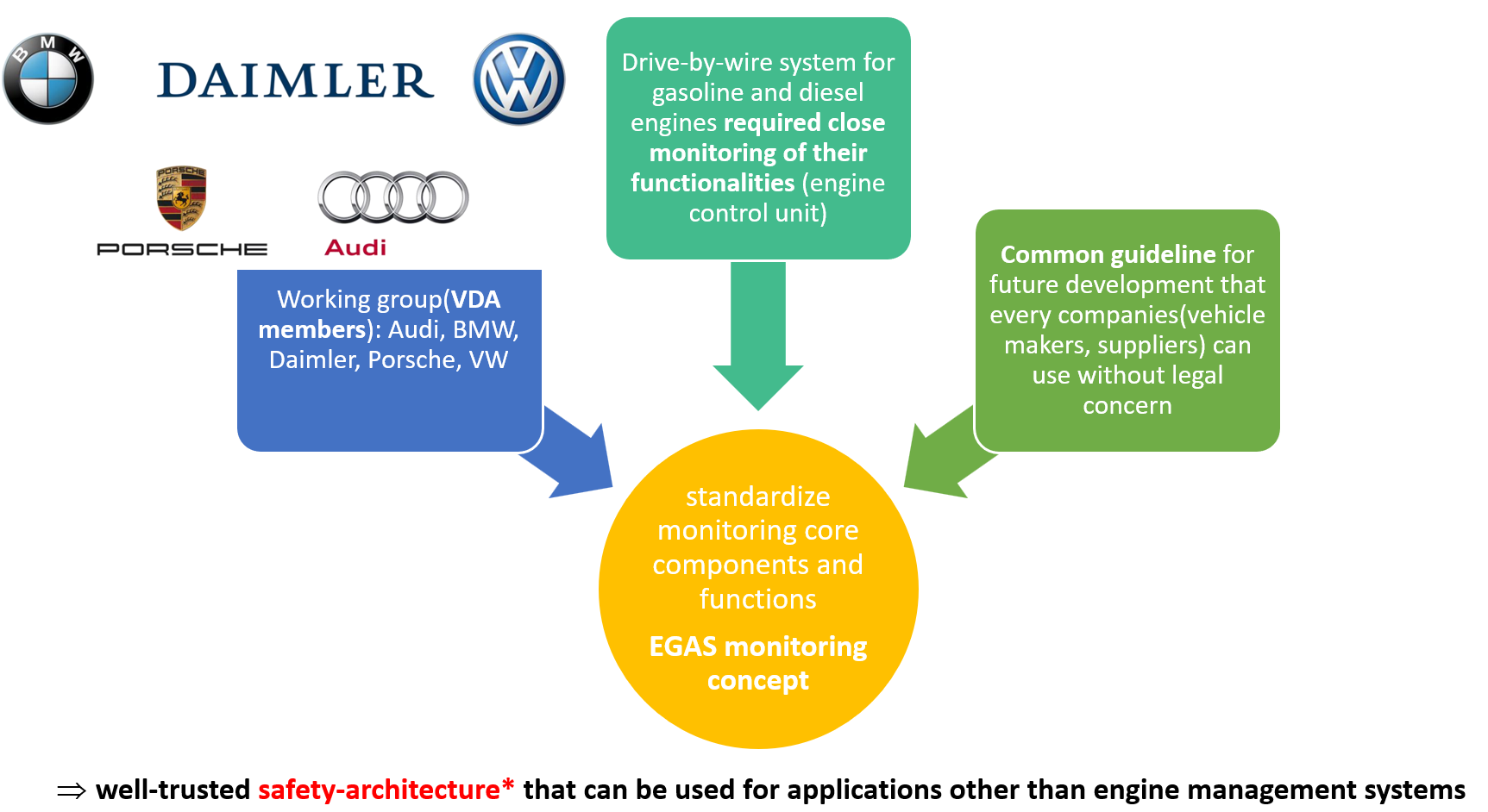
safety-architecture*: EGAS architecture concept is in compliance with the ISO26262 specification. Because of this, you can apply the concept for your functional safety project(other systems in vehicle that required closely monitoring) as a well-trusted design principles.
II. Basic principles
Terminology:
driving cycle: operation time between the key initiate engine start/stop.
fault detection: identification of exceeding permissible deviations of the relevant system parameters leading to a non-fulfillment of at least one requirement regarding a required characteristic.
failure effect: deviation of the system behavior in a faulty condition to the system behavior in a fault-free condition.
failure reaction: the completeness of all initiated measures after the error detection, in order to reduce the failure effect to a permissible limit.
E/E: electrical and electronic.
II.1 Guidelines for development
Below are list of EGAS Developing Guidelines that shall be adhere during development of a system following EGAS concept. Under each guideline item is an further explanation base on my own understanding and experiences.
- Protection of life has the highest priority.
⟹ pretty straight forward, safety of the driver and anyone involve is the most importance. - Reliability has higher priority than backup functions.
⟹ strive for a stable and durable system - The monitoring shall be independent of the engine concept and as far as possible independent of the driver reaction.
⟹ monitoring unit shall not influent anything to system and user. - Functions, in particular for system monitoring (also error reactions), shall be easy and manageable.
⟹ keep it simple. - The system shall be designed so that single errors and single errors in combination with latent errors lead to controllable system reactions. The corresponding signal paths (sensors, actuators, functions) shall be monitored.
⟹ single point fault shall be covered by safety mechanism(1st) and latent fault shall be covered by another level of safety mechanism (2nd mechanism to detect the failure of safety mechanism(1st), which cover the single point fault).
⟹ signal paths(from sensors to the logic processing unit, internal values of control function and control signal to actuators) shall be monitored. - The system shall be designed so that double and dual faults lead to controllable system reaction as required as state-of-the-art.
⟹ required safety mechanism to cover dual-point fault(similar with item 5), not clear the term as state-of-the-art mean (possibly using the newest technology? but it is against ISO26262 recommendation of using well trusted design principles - i.e use of previous used design/system with known failures(so we can predict and prevent) is better than new design/system with new or unknown failures). - In terms of high system availability, staged error reactions shall strive.
⟹ staged error reactions(different level of error reaction), i.e. system can not just stop operate or reset with a minor error, different level of error reaction such as: reset software component, reset tasks, reset MCU’s core, hardware reset MCU, reset whole system(ECU),… - A signal path shall be classified as “confirmed defected” after an explicit detection (e.g. after debouncing event or time) and before the reaction shall be activated. Previously the defect shall be classified as “assumed defect”
⟹ debouncing concept same as diagnostic event debouncing (DEM_EVENT_STATUS_PREFAILED, DEM_EVENT_STATUS_FAILED) in AUTOSAR Diagnostic Event Manager - Appropriate reaction mechanisms shall be defined according to the function in the case of an “assumed defect” and “confirmed defect”.
⟹ each fault/defect shall be mapped with a corresponding safe/degradation operation - The reset of fault reactions shall be determined in individual cases and shall be performed controllable. Non-continuous transitions shall be avoided.
⟹ each fault/defect reaction shall has corresponding healing operation, transition from safe/degradation state to normal operation shall be continuous. - Engine stop is permitted when no other controllable system reaction can be ensured.
⟹ complete shutdown of system actuator is permitted when no controllable safe state can be achieved i.e. priority in term of measures: always try to have the system operational, then degraded/limited function and the last resort is shutdown of system - The transmitter is responsible for the content of its initiated messages at the control unit interface. This means that e.g. external torque requests by the transmitting control unit shall be secured. The transmission path and the actuality of the messages shall be checked by the engine control system.
⟹ the sender of message shall ensure the correctness of the transmitted data. The quality of transmitted data can be checked(to detect any kind of corruption on data either by software or physical transmission path) by applying E2E protection on sender side and E2E check on receiver side. - If errors happen in combination with the subsequent single errors cause unintended system reactions, the driver should be informed. (optically or by modifying the driving behavior).
⟹ detected multiple point faults should be informed to driver via HMI cluster(warning telltale, audio cue) or put vehicle into degraded mode. - The monitoring of the function controller must be kept robust and simple. This includes a possible implementation with an ASIC.
⟹ monitoring of function controller(i.e. logic control unit for intended function) shall be done by external hardware supervisor(i.e. System Basis Chip-SBC or Power Management IC-PMIC, usually semiconductor shall provide these kind of solution along with their MCU/SoC for strict safety system.) - The effectiveness of the redundant shutoff paths shall be tested in each driving cycle.
⟹ test the shutoff path of the actuator (both main function and diagnostic function) working properly should be done for every power on phase i.e. startup diagnostic operation - Shutoff paths of the monitoring concept shall be robust if a defect power supply drifts. The power supply concept shall be monitored to avoid possible damage to components. Controllable failure reactions shall be initiated.
⟹ power supply of system component shall be monitored, same as item 14, usually SBC/PMIC shall provide external hardware supervisor functionalities such as: voltage rail monitor, external watchdog, function controller’s errors monitor - The technical safety concept shall be implemented in accordance with the requirements of ISO26262.
⟹ EGAS concept is in compliance with ISO26262
II.2 The Architecture
Now we will go into system architecture design to cover above principles.With a basic system, we should have inputs(sensor data, communication data,…), processing unit(which carry out control operation and intended functions), outputs(actuators being controlled by the processing unit, causing effect on the outside environment).
If the basic system only care about functioning as its intended, corresponding to the inputs, and able to keep operating consistently over a long period of time then we can say the system is reliable. But upon faulty inputs(user use it wrong, corruption of input data, abnormal operating condition…) or fault that’s rooted from the internal components(part ware down, random faulty E/E part,…), how does the system react? Could it cause a catastrophic failure and effect to the surrounding environment and users ⟹ If so we can say that is not a safe system, reliable might be but not safe.
On the other hand, Safe system beside carry out its intended function, it shall address the reaction of it when failure occur in the system. Safe system shall react properly, make potential dangerous failure become safe failure (i.e. system change to a state that prevent damages that could create hazards toward user).
As said above, when system involve human interaction, we should not design a basic system and only consider its reliability. We should design a system to be safe.
Below table is list of system configuration for example base system(1 out of 1 i.e. 1 logical processing unit, 1 actuator switches(enable/disable output))
| Architecture | No of Logical Processing Unit | No of Actuator Switches | Characteristic |
|---|---|---|---|
| 1oo1 | 1 | 1 | Base system |
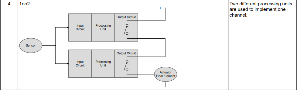
| 1oo2 | 2 | 2 | High Safety |
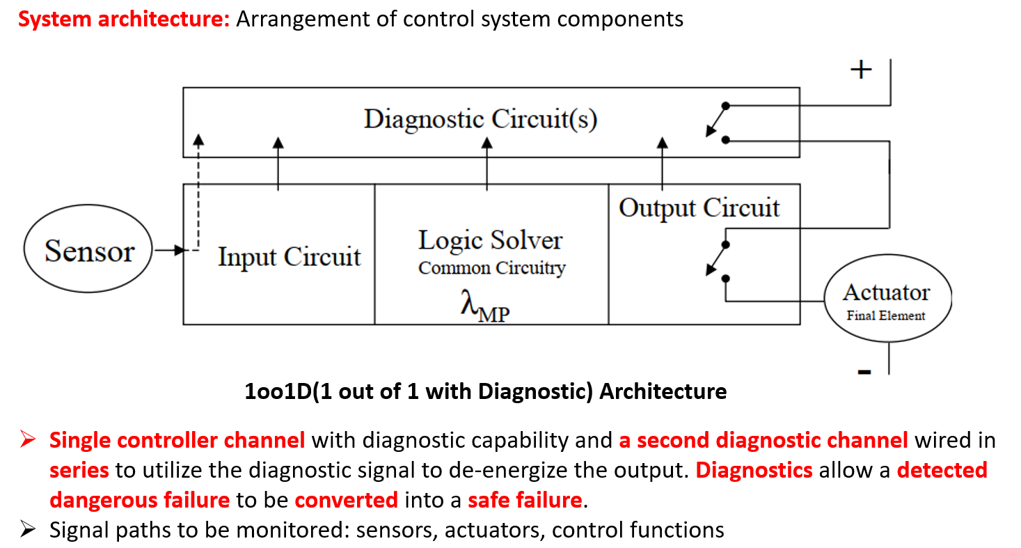
| 1oo1D | 1 | 2 | High Safety |
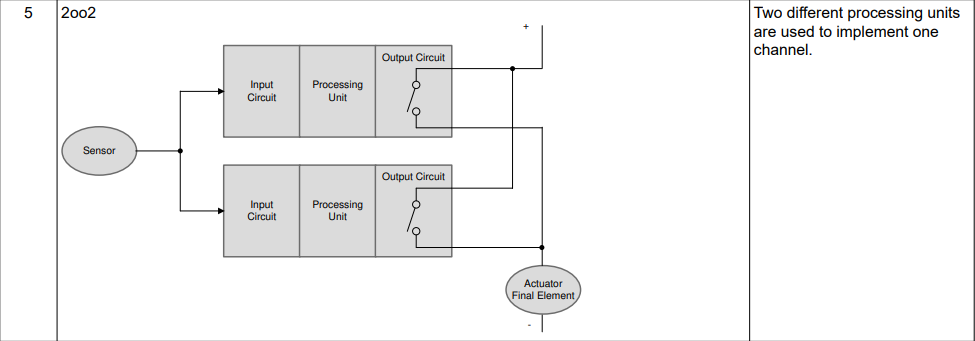
| 2oo2 | 2 | 2 | Availability |
| 1oo2D | 2 | 4 | Safety and Availability |
| 2oo3 | 3 | 6 | Safety and Availability |
*D: diagnostic
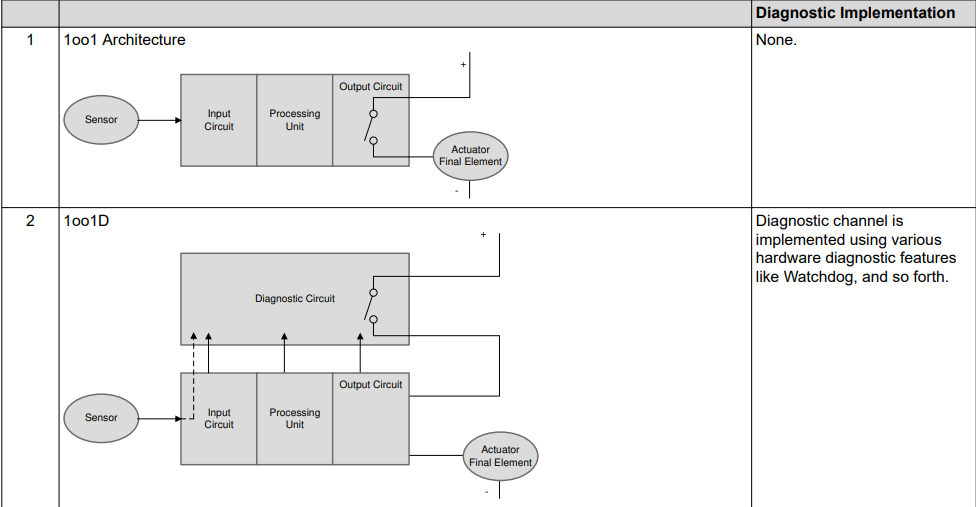
With different configuration of architecture, we can achieve different target in term of availability(keep system available when fault occur) and safety.
We can see that 1oo1D and 1oo2(serial on the output) offer the same “High Safety” characteristic, however 1oo1D configuration provide safety by increasing system diagnostic coverage and does not require a duplication of main processing component as 1oo2. So we lean toward 1oo1D configuration for its simplicity and cheaper to implement(at least for the ASIL B and below system, for ASIL C and D 1oo2D is more referable).
NOTE: Depend on the system target functionality (i.e. when system fail, the system is required to have safety reaction and keep operation=
Safety and Availabilityor move to safe-state without normal function=Safety), the corresponding system configuration should be selected.
For more information about other configuration type of system architecture, you can read more about them in the book “Control Systems Safety Evaluation and Reliability” by William M. Goble
EGAS 3 level system concept
fail-safe: upon the occurrence of a failure, the system shifts into safe mode. Depending on the fail-safe response of the safety mode, it may either continue to be fully operational or not.
fail-silent/fail-degraded/fail-stop: when a failure arises, the system transitions into a safe state, operating at a reduced capacity or ceasing to produce output (becoming silent) to minimize potential damage or hazards. The subsequent preventive action to address the failure should be initiated by the user.
fail-operational: often termed as “fault-tolerant”, a system is designed such that a failure does not halt its overall functionality. Instead, the system reconfigures itself to counterbalance the fault, ensuring continued correct operation.
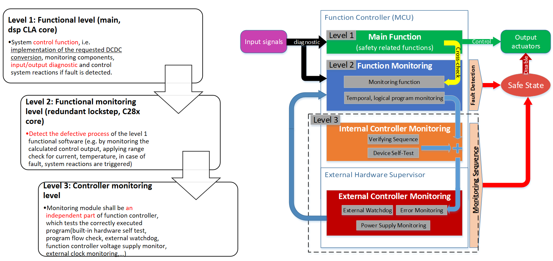
The following image shows the overview of EGAS concept in the specification.
Level 1: functional level, implement primary function, component monitoring, input/output diagnostic and fault reaction of the ECU.
Level 2: function monitoring level, designate to detect defective process of Level 1 functional software by monitoring input/output and operation of Level 1 functional software and trigger system reaction when fault occur.
Level 3: controller monitoring level, monitoring shall be an independent part of Level 1 function controller, which test the correctness of Level 1 function controller with Q&A operation. System reactions are triggered independently of the function controller in case of fault.
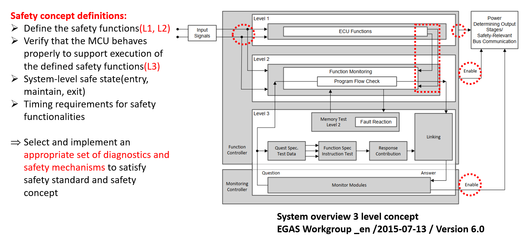
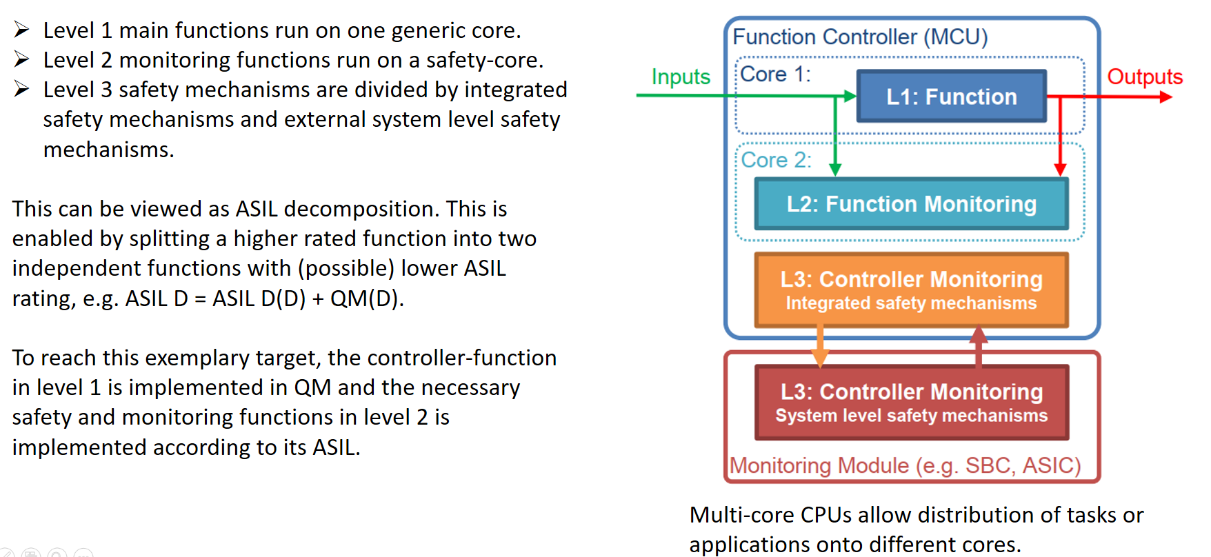
We can see that EGAS concept follow the 1oo1D system configuration, with level 2 and 3 act as diagnostic channel of ECU primary function level 1.
And the red circle highlights are point of monitoring for signal paths and output actuator control point of fail-safe reaction.
III. Example System
For our example, we shall consider a DCDC power converter system. As said above, EGAS concept compliance with ISO26262, so the analysis and design of system shall following all the step define in ISO26262.
III.1 System Definition (Item Definition)
For system(item) definition, we should define and describe item’s functionalities, dependencies on and interaction(interfaces) with user, environment(conditions) and other item in vehicle.
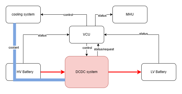
NOTE: Usually, the Item Definition should be carried out at the vehicle level, with the target is to define a vehicle functionality (a collection of systems that realize a vehicle functionality) as above image.
Functional characteristics:
Convert High Voltage Direct Current(from HV Battery supply) power to Low Voltage Direct Current power to supply LV components in vehicle
Structure:
➢ DCDC shall take DC HV power supply from HV Battery of vehicle.
➢ DCDC shall output DC LV voltage, current to supply the LV system of vehicle base on Vehicle command.
➢ DCDC power circuit shall be controlled by DCDC MCU.
Components:
➢ Inputs and input sensors: Input HV Power, HV Voltage sensor, HV Current sensor, Control request signal(LV Output power setpoint) from user(e.g. VCU, HPC), Internal Temperature sensor(for monitoring switching semiconductor components, inductor,… which could produce heat during operation and need to be monitored so system can react properly)
➢ System components:
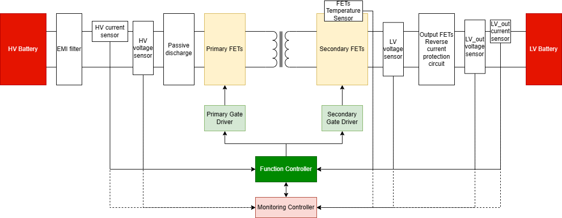
➢ 1. Power electronic circuit: DCDC Converter phase shifted full brigde circuit (primary side FETs & gate driver, secondary FETs & gate driver, isolation transformer,…)
➢ 2. Logical processing unit: DCDC controller MCU for closed control loop operation.
➢ 3. Power supply unit: Provide power for the operation of other electronic components(MCU, switching FETs, gate driver) in the system.
➢ 4. External hardware supervisor unit: Redundant monitoring unit, which shall responsible for monitoring system power rail, processing unit.
➢ Outputs and output sensors: Output LV Power, LV Voltage sensor, LV Current sensor
Interfaces with other items: HV Battery/BMS, LV Battery, Cooling System, Vehicle Control Unit or Powertrain High Performance Computer unit.
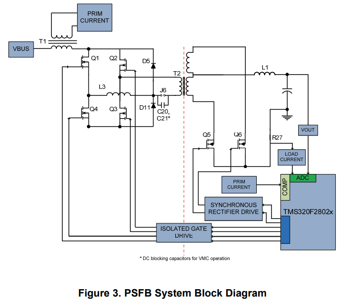 DCDC PSFB converter consists of four power electronic switches (like MOSFETs or IGBTs) that form a full bridge on the primary side of the isolation transformer and diode rectifiers or MOSFET switches for synchronous rectification (SR) on the secondary side.
III.2 Hazard Analysis and Hazard Assessment (HARA)
For hazard analysis and risk assessment, the system functionalities are analyzed in every possible operating conditions/situations and risks of the system is determined. By apply guide words(HAZOP) in combination with system's functional behavior, for example: Excessive, Insufficient, Loss, Degraded, Intermittent, Erratic, Oscillitory, Undemanded, Reversed, Late, Early, Lack,… we can list out potential failure behaviors systematically.
Then apply these failures with possible operating condition, we get the output result are hazardous events, which shall be evaluated with respect to severity(S), probability of exposure(E) and controllability(C) and given with an ASIL rate.
Finally, we shall come up with safety goals to cover for those hazardous events. Safety goals shall be functional objectives of the system and top-level safety requirement of the item, in term of technical solutions, safety goals shall be specified in Function Safety Concepts(FSC) and Functional Safety Requirements(FSR) to avoid unreasonable risk of each hazardous events.
For our example, below is list of safety goals of DCDC system:
SG1: Prevention of unintended thermal release
SG2: Prevention of unintended electrocution
SG3: Prevention of insufficient voltage output
SG4: Prevention of excessive voltage output
For the hazards that cause uncontrollable and hazardous events in vehicle, they required monitoring concept to transfer the vehicle into a controllable and safe state. (EGAS_e-87, EGAS_e-88)
III.3 Functional Safety Concept (FSC/FSR)
To keep it short, we will only create sample analysis of the first SG1 to provide inputs for explaining EGAS concept
SG1: Prevention of unintended thermal release: with DCDC converter circuit, heat shall be produced by power switching FETs components and the isolation transformer during system operation.
⟹ FSC/FSR to cover this safety goals
red: system might produce heat during the power conversion operation -> target of our safety goals. But in this blog we shall only address the DCDC system.
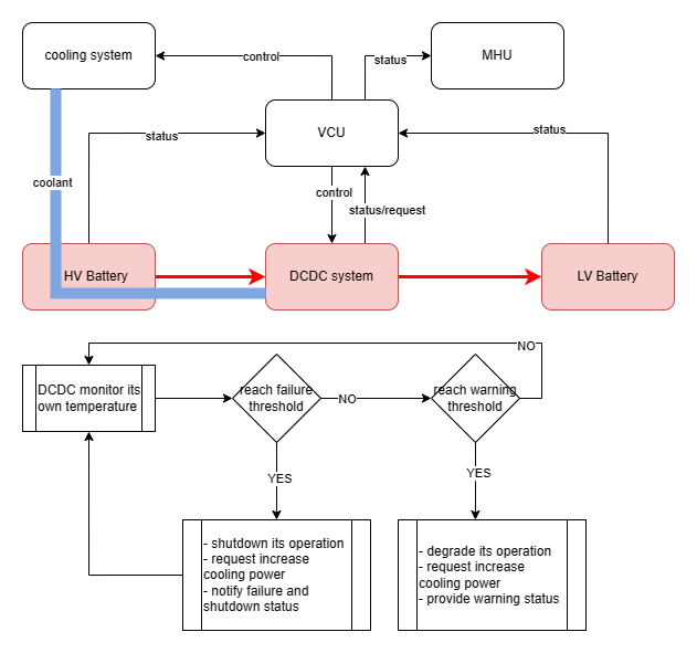
Fault avoidance, degradation of functionality: temperature of the DCDC converter system shall be monitored during its operation, when its internal temperature reach [WARNING_THRESHOLD] degrade the system performance/output, request increase cooling to vehicle thermal control system, provide warning status to vehicle HMI and audio warning cue[FSR_001].Fault detection, control, transition to safe state: temperature of the DCDC converter system shall be monitored during its operation, when its internal temperature reach [FAILURE_THRESHOLD] trigger shutdown sequence of the system, request increase cooling to vehicle thermal control system, provide warning status to vehicle HMI and audio warning cue[FSR_002].
III.4 Technical Safety Concept (TSC/TSR)
So we have the FSC and 2 FSRs, along with our pre-defined system architecture design(*III:DCDC system block diagram) -> system level safety TSC/TSR shall be derived from these inputs and incorporated back to system architecture.
The technical safety concept/safety mechanism design on the system level shall follow 3 level concept as discussed in previous section.
Now apply above concept into our target system, we have 3 main section of the safety signal path need to be monitored: sensors, processing unit, actuators.
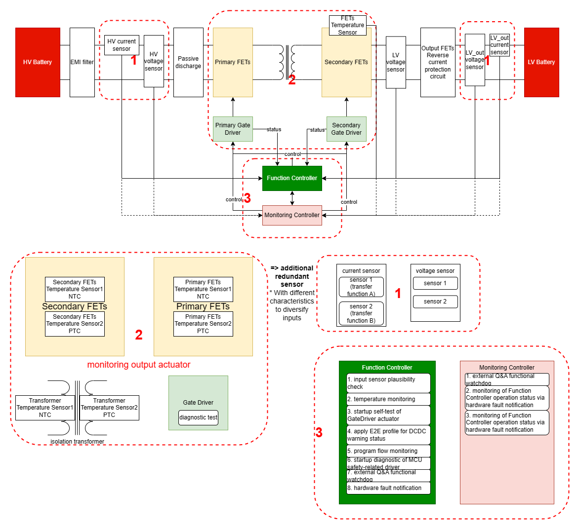
Section 1: for the safety related input sensors, safety mechanisms can be applied such as:
- sensor redundancy(with different curve characteristic, separated physical signal path, power supply to eliminate common cause fault)
[Level1] - employ/design sensor device/circuit with diagnostic capability(check shorted, open).
[Level1]
Section 2: for the output actuator, safety mechanisms can be applied such as:
- monitor operation status of the actuators.
[Level1] - employ/design feedback of output actuator control signal or actuator with diagnostic capability for self-test purposes
[Level1]
Section 3: for the processing unit,
- perform plausibility check, cross-check, range-check on input sensor signals.
[Level1], [Level2] - apply signal protection(E2E profile) to safety related digital communication signals (warning status, control signals send/receive from other components).
[Level1], [Level2]
⟹ signal inputs for primary functions, monitored by Level2 as well
- perform diagnostic self-test on actuators in startup(.e.g shutoff path test).
[Level2] - base on validated input sensors, actuators feedback, and primary function control output, perform safety monitoring: operating status,
output control signal-> toensure Level 1 system's primary functionoperates in permissible state (i.e. allowed operation threshold vs actual/current operation output or state).[Level2] - program flow monitoring of Level2 safety modules, watchdog management(external hardware watchdog or functional watchdog Q&A).
[Level3] - Monitoring Controller(physical independent monitoring module) perform monitor(Q&A watchdog, statuses) Functional Controller operating status.
[Level3] - perform diagnostic self-test mechanism(Power On Self Test-POST) of Functional Controller semiconductor in startup (diagnostic coverage) i.e. RAM, ROM, CPU BIST, peripheral test(ADC, CLK, GPIO,..),etc.
[Level3]
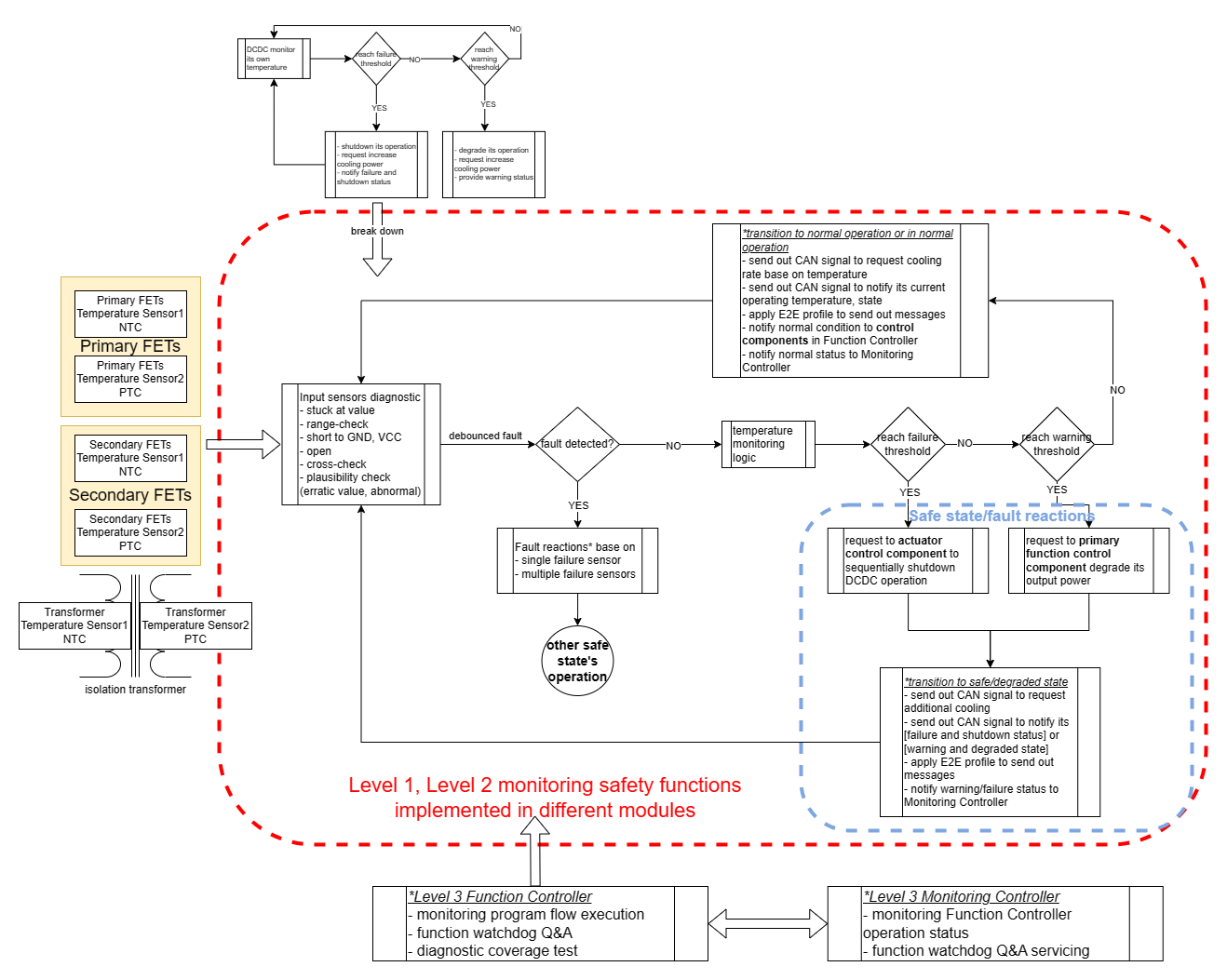
III.5 System Reactions (Fault Handling - Safe State)
As stated by previous guideline items: for fault handling - safe state, staged error reactions shall be strived.
⟹ every failures shall be mapped with their corresponding reaction, reaction should try to isolate/resolve the fault locally(prevent fault propagation). If fault has direct impact on primary functionality, last resort actions such as shutoff actuators, reset whole system shall be used.
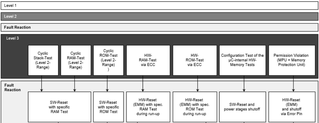
Example for Level 3 fault reaction as below: 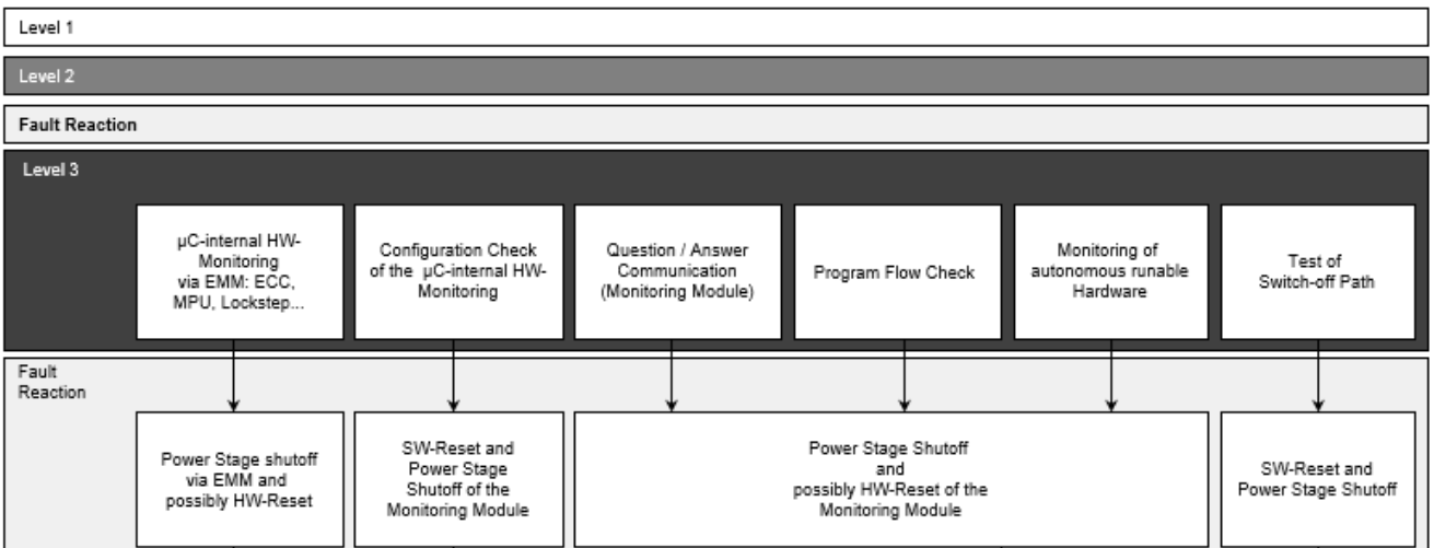
IV. Conclusion
Generally, the EGAS concept adheres to the 1oo1D system configuration, which involves monitoring the primary function and diagnosing the safety signal path. Any identified faults are addressed appropriately through a staged error reaction, causing the system to transition into a fail-silent, fail-degraded, or fail-stop state..
⟹ a good design concept to be adopted for ASIL B (and lower safety integrity system).
As the automotive world evolves with intricate features like ADAS and autonomous driving, the demand for fail-operational systems is also on the rise. Therefore, it would be beneficial to explore safety architecture designs from other fields, such as avionics, to comprehend, adapt, and customize existing technical solutions and design principles and apply it to our automotive system.