Electric Vehicle Charging Overview
With the advancement of Electric Vehicle, come along charging standards that specify the Charging Station requirements, their interfaces and communication aspect between EV and Power Supply System/EV Charging Station.
This blog is a summarized record about types of electric vehicle charging station, its charging methods, connector guns, modes of charging, compliance testing and certification standards.
EV: Electric Vehicles that have battery energy storage (sometimes referred to as Battery Electric Vehicle, BEV). This includes PHEV (Plugin Hybrid EV).
EVSE: Electrical Vehicle Supply Equipment. The logical unit in a Charge Point/Charging Station that supplies electric energy via a Connector for charging. An EVSE can have one or multiple Connector(s).
EVCC & SECC: Electric Vehicle Communication Controller and Supply Equipment Communication Controller. These are the components on the vehicle and charger sides, which responsible for handshaking, controlling, safety monitoring, and digital communication.
OBC: Vehicle On-Board Charging Units, responsible for receiving AC power and convert it to DC and charge Vehicle HV Battery.
NOTE: version of standards addressed in this blog: CHAdeMO-2.0, ISO15118-2019, IEC 61851-2017, GB/T 2015, J1772-2017, NACS-2022
I. Types of Electric Vehicle Charging
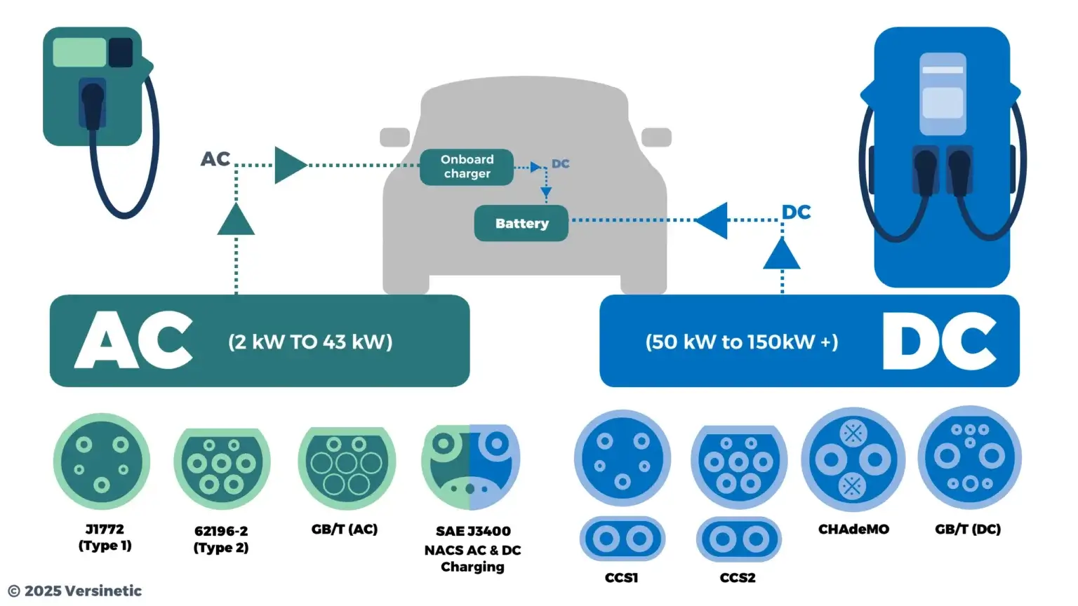
I.1. AC Charging
With AC charging, EV shall use it own Onboard Charger to receive and convert AC to DC energy and charge its High Voltage Battery, where Charging Station EVSE is more like a controlled smart switch with safety and monitoring features.
According to SAE standard J1772(adopted in North America, Japan market), they classify AC Charging into 2 level:
Level 1(low power):- Charging uses a standard
household outletwith NEMA 5-15R or NEMA 5-20R plug. - 1-phase 120V, max current 16A, directly from AC supply network.
In-cable control box(ICCB)on power cord set to provide simple charging communication and control viacontrol pilotline.Type 1charging gun connector.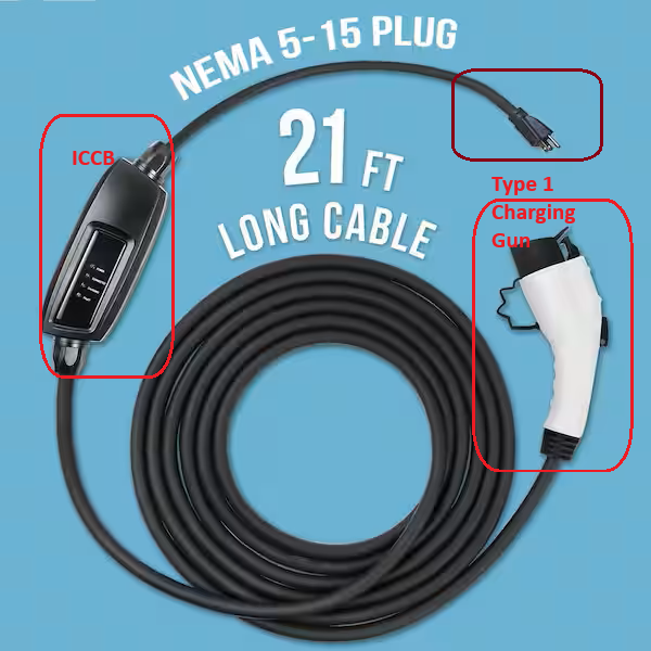
- Charging uses a standard
Level 2(high power):- Home or commercial installation with
dedicated supply equipment(EVSE/SECC) components, operates at higher voltage and current, deliver power between 3 kW and 22 kW. Fixed place installation, which is permanently connected to 208V wye(Y) 3-phase or 240V split phase, max current ≤ 80A.- Same charging communication and control via
control pilotline withType 1charging gun connector.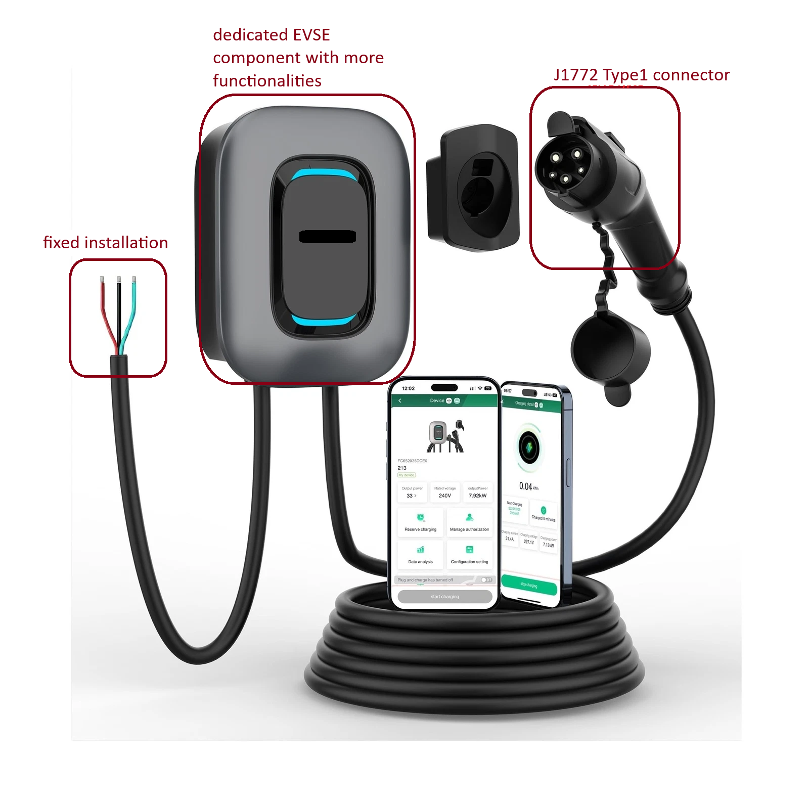
- Home or commercial installation with
For European/International standard IEC-61851 (same for China standard GB/T 18487.1), they classify 3 modes that fall in AC charging category:
Mode 1charging (low power):- Direct connection to AC supply network(household) via standard plug/socket-outlet.
- 16A, 250V(single-phase) or 480V(three-phase).
No charging communication and controlonly passive AC power connection and supplying circuit shall be provided with an Residual Current Protection(RCP).- Normally used for
Light EVs(e.g. bike)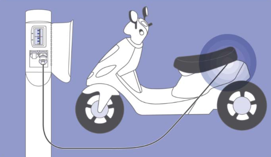
Mode 2charging (low power):- Charging cable is equipped with an
in-cable control box(ICCB), which includes communication and control viacontrol pilotline and safety related functionalities such as restriction of the charging current, fault protection, PE, RCP. - 32A, 250V(single-phase) or 480V(three-phase).
Type 2charging gun connector.
- Charging cable is equipped with an
Mode 3charging (high power):Fixed installation, permanently connected to an AC supply network.- 1- or 3-phase charging with AC up to 3x63 A or 1x70 A
- Same communication specification via
control pilotline, extended safety and control functionalities with dedicated EVSE withType 2charging gun connector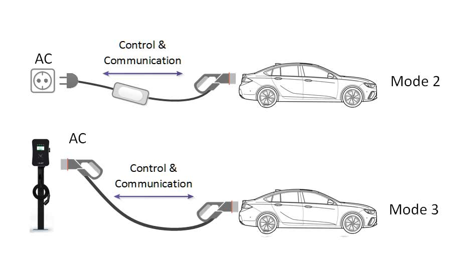
Summary
| Feature | SAE J1772 Level 1 | SAE J1772 Level 2 | IEC 61851 Mode 1 | IEC 61851 Mode 2 | IEC 61851 Mode 3 |
|---|---|---|---|---|---|
| Supply Type | 1-phase AC | 1, split-phase AC | 1, 3-phase AC | 1, 3-phase AC | 1, 3-phase AC |
| Voltage Range | 120 V AC | 208–240 V AC | 250V(1-phase) or 480V(3-phase) | 250V(1-phase) or 480V(3-phase) | 250V(1-phase) or 480V(3-phase) |
| Max Current | ~12–16 A | Up to 80 A | ≤16 A | ≤32 A | ≤63 or 70A |
| Max Power | ~1.4–1.9 kW | Up to 19.2 kW | ~3.7 kW | ~7.4 kW | Up to 43.5 kW |
| Connector Type | ICCB and J1772 Type 1 | dedicated EVSE and J1772 Type1 | Standard plug | ICCB and IEC 61851 Type 2 | dedicated EVSE, IEC 61851 Type2 |
| Control Pilot / Communication | Yes (PWM duty cycle per J1772 spec) | Yes (same as Level 1) | None | Basic control (via ICCB) | Full Control Pilot (IEC 61851 PWM signaling) |
| Installation | Standard household outlet | Dedicated 240 V circuit | Domestic wall socket | Domestic socket + control box | Dedicated AC supply circuit and EVSE |
| Use Case | Portable slow charging | Home or public fast AC | Legacy/basic charging for Bike | Portable or emergency charging | Standard public or wallbox charging |
| Safety Level | Basic | Higher (with EVSE control) | Minimal control, low safety | In-cable control and protection device (IC-CPD) | High (full control & protection) |
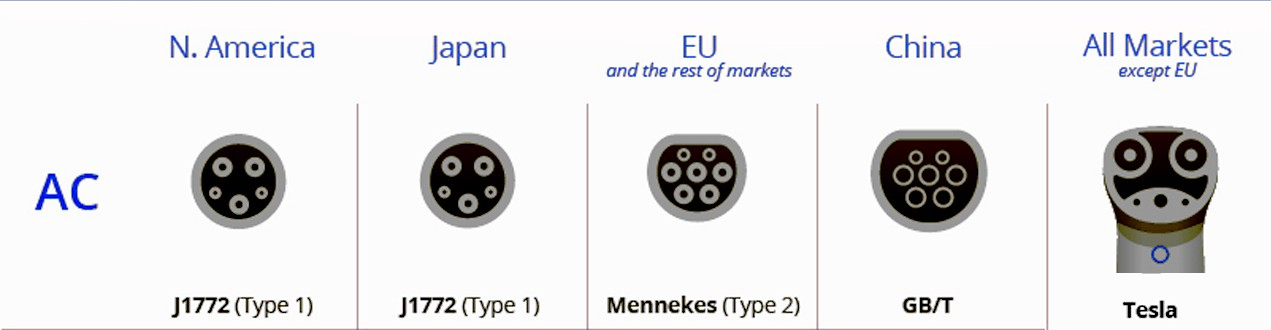
NOTE: for Tesla, they follow North American Charging Standard
(NACS) TS-0023666, despite different in term of physical design of charging interface as in image above, it compatible with IEC 61851-1 (utilize the same basic signal communication method via control pilot line).Higher current = larger charging cord/cable size.
Usually charging cable should come with aresistor in the proximity linethatcoded the maximum current capacityof cable assembly. (proximity line is a pin in charging interface, as the name it help to indicate insertion status between charge plug and socket)
I.2. DC Fast Charging
Unlike AC charging, where the vehicle’s Onboard Charger (OBC) converts power, with DC Fast Charging, Charging Station responsible for converting Grid AC to DC and delivers DC electricity directly to the vehicle's HV battery. This allows for significantly higher power levels and faster charging speeds since the high-power power electronic components have more space and reside close to grid.
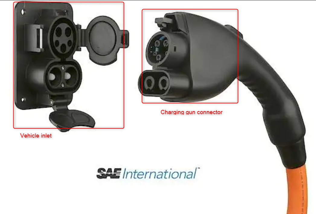
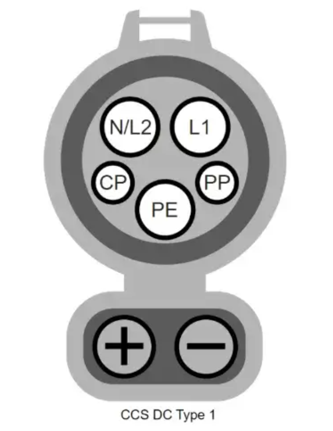
For SAE J1772 (North America) standard, the DC fast charging use the Combined Charging System Combo 1 (CCS1), which add two large DC pins right under the J1772 AC Type 1 inlet. This allows both AC and DC on one vehicle port.
- 2 level of DC fast charging with different power rating: 1000V - up to 80A(Level 1) or - up to 400A(Level 2), so maximum power delivery ~400kW
- Charging communication utilize the same
Basic Control Pilot (PWM)with additionalhigh level communicationinjected on Control Pilot line viaPower-Line Communication(PLC)signal (same as ISO 15118 or DIN 70121).
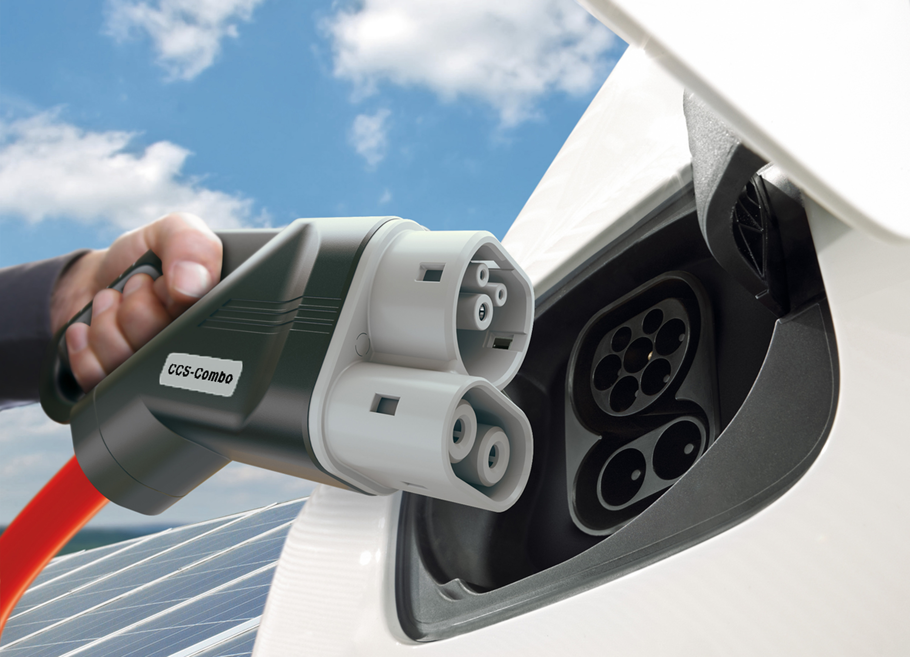
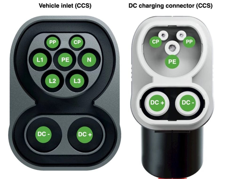
For European/International standard IEC 61851, DC fast charging is defined as Mode 4 (System C, combined charging system). Similar to SAE J1772, the DC charging use the Combined Charging System Combo 2 (CCS2), which extend the Type 2 AC charging interface with 2 additional DC pins right under the AC port.
- Power rating: 1000–1500V and up to 200–400A.
- Charging communication use PWM Control Pilot (low-level) + high-level digital comms via PLC (IEC 61851-24 / ISO 15118) for advanced control and V2G support.
Japan has their own DC charging standard, which is CHAdeMO. It uses a separate, non-combined connector(refer to figure below) i.e. not backward-compatible with AC in their market(i.e. the SAE J1772).
It was also one of the earliest DC standards that define bidirectional charging (V2L, V2H).
- Power rating: 1000V and up to 400A.
- Charging communication is done through CAN protocol with dedicated CAN line and other charging sequence line in the charging cable assembly.
- CHAdeMO charger also provide 12VDC supply to vehicle, so it can use and operate the vehicle relay(DC contactor to HV battery).
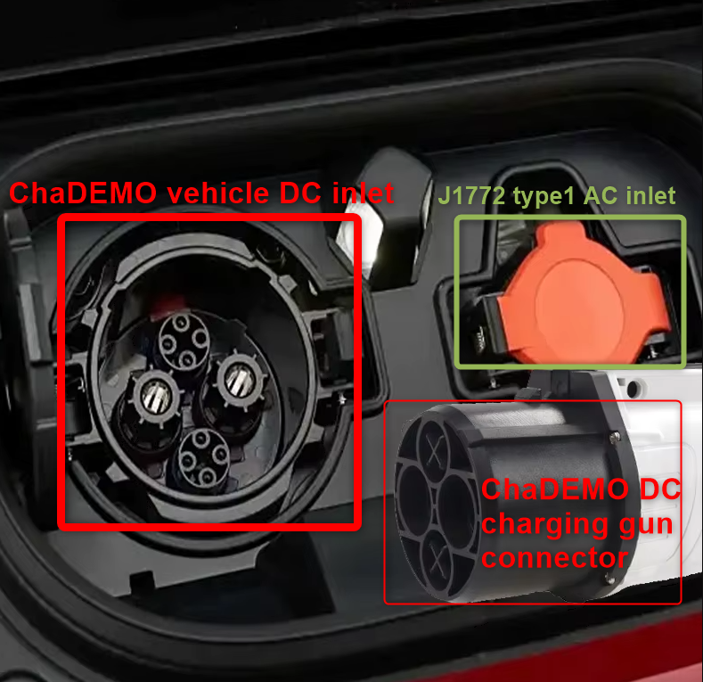
In IEC61851 standard, CHAdeMO DC charging is addressed as
system A.
China's national GB/T standard(GB/T 18487.1) also define their own dedicated charging standard for DC fast charging, separate from its AC standard and interface(refer to figure below).
- Power rating: voltage 750–1500 V DC and current 250–800 A.
- Same as CHAdeMO, GB/T charging communication is also done with charging confirmation signal lines and CAN bus line(CAN communication is utilize SAE J1939 protocol instead of specific data-link level CAN frame on CHAdeMO)
- GB/T also provide a Low-voltage auxiliary line from charger to vehicle
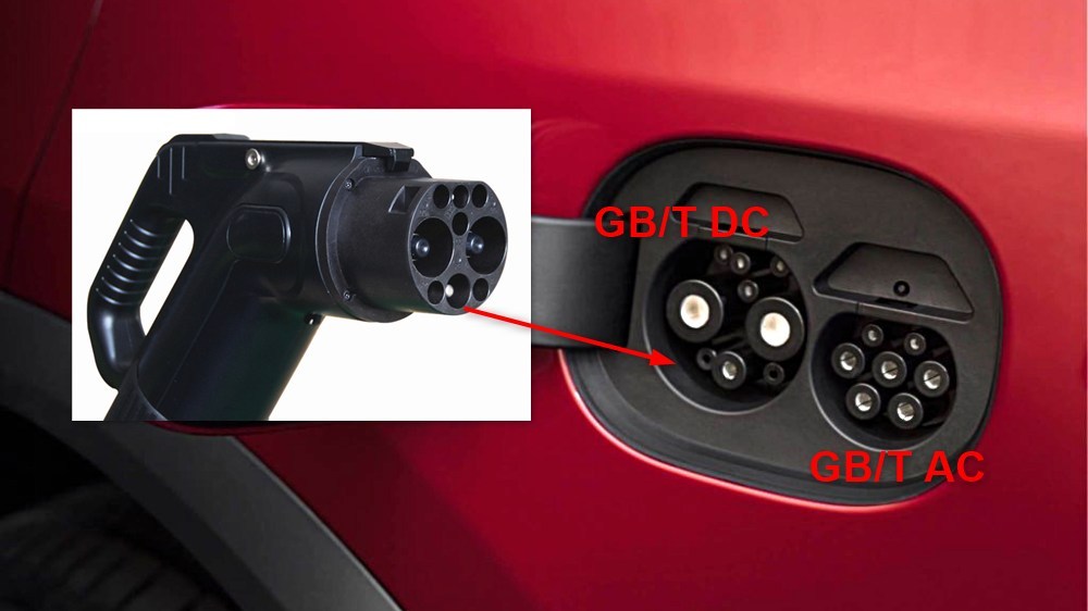
In IEC61851 standard, GB/T DC charging is addressed as
system B.
⟹ All of the above DC fast charging standard expected strict insulation monitoring, RCDs, thermal management, interlock control, fault monitoring and safety/protection mechanism, which are required on both Charging Station and EV side.
| Standard | Connector Type | Max Voltage | Max Current | Max Power | Region | Communication |
|---|---|---|---|---|---|---|
| SAE J1772/CCS1 | CCS1 | ~1000 V | 400–500 A | 350 kW+ | North America | Control Pilot PWM + PLC/ISO 15118 |
| IEC 61851 (Mode 4) | CCS2 | 1000–1500 V | 200–400 A | 50–350+ kW | Global/Europe | Control Pilot PWM + PLC/ISO 15118 |
| CHAdeMO | Dedicated DC interface | 500–1000 V | 125–400 A | 62.5–400 kW | Japan/legacy | CAN bus (raw CAN frame) |
| GB/T | Dedicated DC interface | 750–1500 V | 250–800 A | 250–1200 kW | China | CAN bus (J1939 as baseline protocol) |
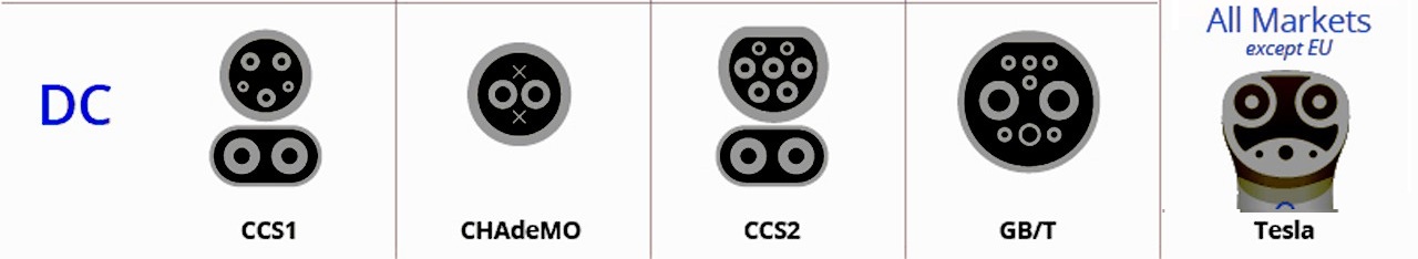
NOTE: for Tesla, the
NACS TS-0023666also address DC charging, power transfer and communicationutilize the same AC charging interface, and its communication compatible with DIN70121 and ISO15118.
CHAdeMO and GB/T work in conjunction to release their common charging standardChaoJi(aka CHAdeMO 3.0 release in 2021)
I.3. Wireless / Inductive Charging
Wireless Power Transfer (WPT) eliminates physical connectors using magnetic resonance and induction. Charging Station shall have a primary coil(Ground Assembly) creates a magnetic field, which induces a current in a secondary coil on the EV.
The charging power rate is similar to AC charing, which is around 11kW.
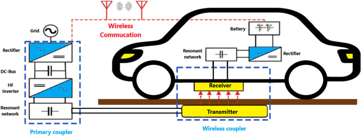
Standards that define Wireless power transfer system:
IEC 61980-1: General requirements for WPT systems.IEC 61980-2: Communication between EV and infrastructure regarding WPT.IEC 61980-3: Specific requirements for magnetic field power transfer.
II. EV Connector Types
II.1. Type 1 (SAE J1772)
- Region: North America, Japan, South Korea.
- Type: AC Single-phase or Split-phase

- Pins:
- L1: AC power line
- L2 or N: neutral(single phase) or AC power line(split phase)
- PE: protective earth
- CP: control pilot line(basic signalling with PWM and voltage level control)
- PP: proximity line
II.2. Type 2 (Mennekes / IEC 62196-2 / GB/T 20234 AC)
- Region: Europe, Global International.
- Type: AC Single or Three-Phase.
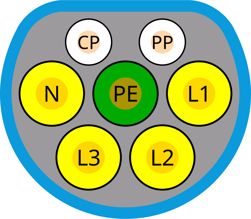
- Pins: 7 pins
- L1, L2, L3: AC power line (phase1-3), if charging station only support 1 phase AC then L1 shall be used.
- N: neutral
- PE: protective earth
- CP: control pilot line(basic signalling with PWM and voltage level control)
- PP: proximity line
II.3. CCS (Combined Charging System)
CCS is an extension of Type 1 and Type 2 connectors, adding two large DC pins at the bottom for high-voltage fast charging.
- CCS Type 1: Used in North America. Combines J1772 (top) with DC pins.
- CCS Type 2: Used in Europe. Combines Mennekes (top) with DC pins. The AC pins on the top could be retain or remove depend on capability of Charger(i.e. they could support both AC and DC charging or not, normally Charger either support AC or DC only).
II.4. CHAdeMO
- Region: Japan (global adoption in early EVs like Nissan Leaf).
- Type: DC only.

- Pins:
- DC+/DC-: DC power supplied power
- FG (PE): Ground reference for control lines
- SS1/SS2: Charge sequence signal 1, 2 for start/stop charging
- N/C: Reserved, not connected.
- DCP: Charging enable, vehicle grants EVSE permission to connect power
- PP: Connector proximity detection charge interlock, disables drivetrain while connected
- C-H/C-L: CAN bus communication with vehicle bus to establish operational parameters
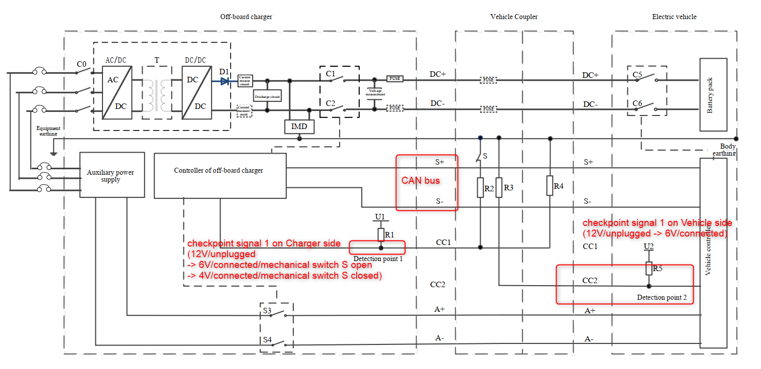
II.5. GB/T 20234 DC
- Region: China.
- Type: DC only.
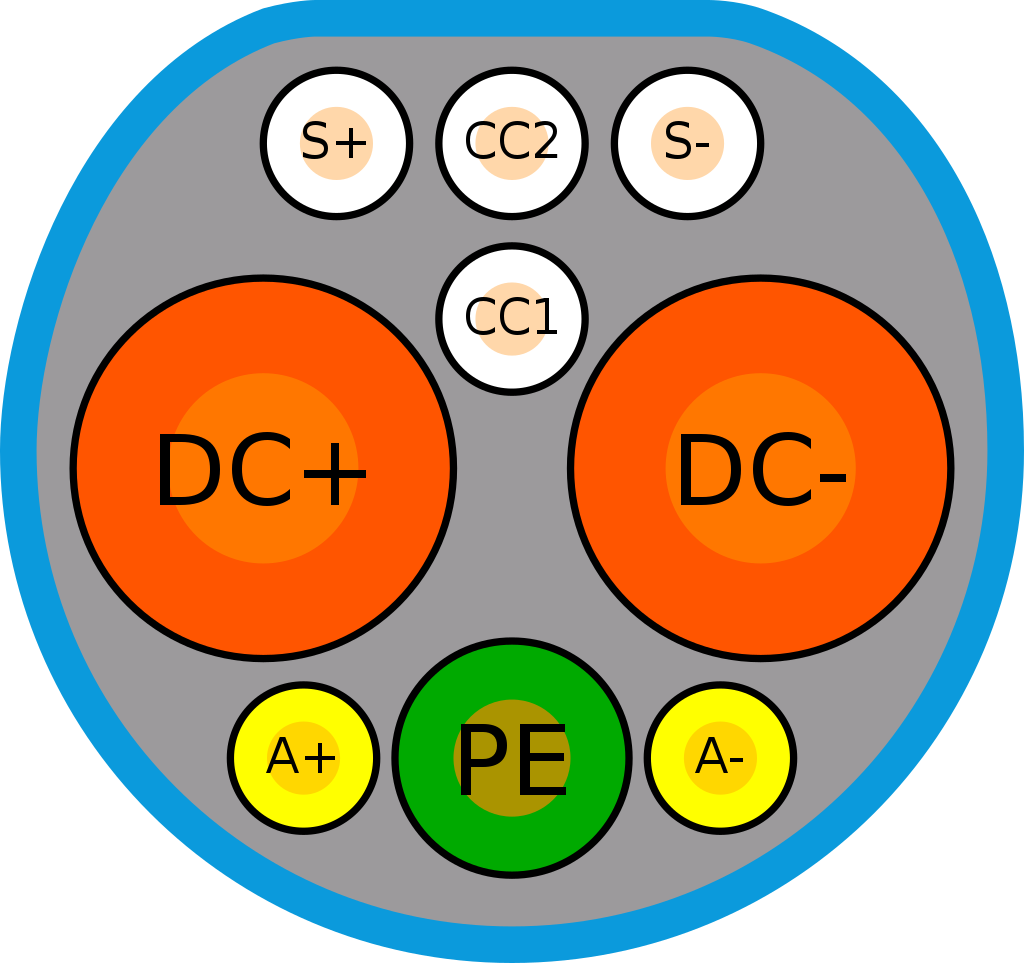
- Pins:
- S+, S-: CAN-H and CAN-L signal line
- CC1, CC2: charging control(charging check point) or connection confirm signal
- DC+, DC-: DC power line
- PE : protective earth
- A+, A-: auxiliary power supply, 12V low voltage to supply the charging circuit on Vehicle side
II.6. Tesla Proprietary Connector (NACS)
- Region: Primarily North America for Tesla vehicle and their super charger.
- Type: Combined AC and DC (same pins for both AC and DC charging).
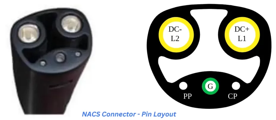
- Pins:
- DC+(L1), DC-(L2): AC power line (single phase or split-phase) or DC power line.
- G: grounding/protective earth
- CP: control pilot line(basic signalling with PWM and voltage level control)
- PP: proximity line
Connector Summary
| Connector | AC Support | DC Support | Primary Region | Communication Protocol |
|---|---|---|---|---|
| Type 1 | Yes (1-phase, split-phase) | No | USA, Japan | PWM / PLC(optional) |
| Type 2 | Yes (1/3-phase) | No | Europe | PWM / PLC(optional) |
| CCS 1 | Yes | Yes | USA | PWM / PLC (GreenPHY) |
| CCS 2 | Yes | Yes | Europe | PWM / PLC (GreenPHY) |
| CHAdeMO | No | Yes | Japan | CAN Bus |
| GB/T DC | No | Yes | China | CAN Bus (J1939) |
| NACS | Yes | Yes | USA (Tesla) | PWM / PLC (GreenPHY) |
III. Communication Standards
So how do charging station and EV communicate to coordinate their power transfer operation?
Those information will be transfer via communication pin and bus protocol, which we have mention in above, and we shall have a quick overview of those communication standards in this section.
III.1. Basic Signaling on Control Pilot line (IEC 61851-1, SAE J1772, GB/T 18487.1_AC)
Control Pilot is the mandatory communication line defined in IEC 61851-1, GB/T 18487.1 and SAE J1772 for AC charging. Charging Station and EV convey information and coordinate the AC charging session via this control pilot and proximity line.
- Proximity line: is used to signal that the charging gun connector has made physical connection to vehicle inlet. Also vehicle can
interpret the maximum current transfer capabilityof the charging assembly by measuring the voltage level on this pin (charging cord has a current coding resistor inside it).
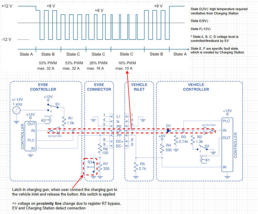
- PWM Signal on Control Pilot line: Charging Station generate and modulate the duty cycle of 1 kHz ±12 V PWM signal over the Control Pilot line.
EV then measure the duty cycle of PWM signal to interpret what is the maximum available current it can draw from Charging Station (e.g. 10%–96% duty cycle maps to specific amperage values like 6 A to 80 A) - Voltage Level of PWM signal on Control Pilot line: So Charging Station can convey the information via PWM signal and it’s duty cycle, then how EV can feedback the signal to Charging Station?
-> EV side circuit have a Diode on CP line and it create a voltage drop on CP PWM signal by apply additional register on its side, Charging Stations then measure the discrete voltage level of PWM positive state signal to interpret what state of charging that EV are in or fault status.
More detailed description of Basic Signalling communication on Control Pilot line can be found here [TBD]
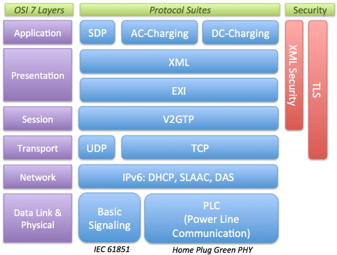
III.2. Power Line Communication and High Level Communication protocol (ISO 15118, SAE J2931, DIN 70121)
In case of DC charging(for NACS, J1772 or IEC61851), beside Basic Signalling on Control Pilot, High-level communication(HLC) is also a mandatory digital communication protocol for bidirectional communication between EV an charging stations. HLC message is injected on control pilot line via under layer HomePlug Green PHY(Ethernet II) power line(PLC) signal.
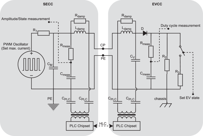
When Charging Station support HLC communication on Control Pilot line, it usually generate 5% duty cycle PWM to indicate to vehicle that it support PLC and HLC communication.
HLC is mandatory for DC charging station andoptional for AC chargingstation (NACS, J1772, IEC61851)
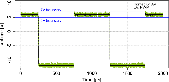
HLC protocol(V2G) is then build on top of standard Ethernet stack, the only different is the transceiver(.e.g Broadcom QCA7000) and the transmission physical medium(power line via Control Pilot)
NOTE: V2G HLC and underlayer PHY PLC are injected signal on the Control Pilot line doesn’t mean it work independently with Basic Signalling PWM on Control Pilot line.
They are tightly coupled: Basic Signalling PWM provides continuous basic safety via analog signal state level, while HLC add digital communication on the same line for other advanced and value added features such as Internet Access, Billing, Metering, Plug and Charge, etc.

More detailed description of ISO15118 Power Line Communication and High Level Communication(V2G) protocol can be found here [TBD]
III.3. CHAdeMO communication
In CHAdeMO standard, charger and vehicle coordinate their changing session (initiate, exchange the charging control and management information) via proximity pin, charge sequence/permission pins signal and CAN bus with a predefined collection of CAN frame(CAN 2.0B).
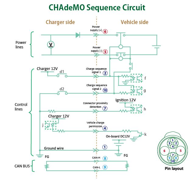
The usage of charge sequence signals, proximity, charging enable/disable and CAN frame are intertwined during a charging session.
We can clearly see the usage of 4 independent signal lines:
⑦: help both Charger and Vehicle detect charging gun connector has connected to vehicle inlet
②: Charger initiate the handshake sequence with Vehicle
④: Vehicle is ready after handshake sequence, grant permission to Charger to output power and start the charging loop sequence.
⑩: Charger has completed it pre-charge and insulation test and now start output power. Vehicle now can close its DCFC contactors and start receiving power (as the circuit line supply power to DCFC contactor operation from Charger is now completed when d10 switch closed).

CHAdeMO use extra charge sequence/permission signals, along with charge control message from CAN message to increase it reliability during start/stop phase.
Hence requires additional cross-check between signal lines and CAN signal to detect inconsistency logic between them.
More detailed description of CHAdeMO CAN communication can be found here [TBD]
III.4. GB/T 27930 communication
For the GB/T DC charging the communication is defined in GB/T 18487.1 DC appendix and detailed communication messages are defined in GB/T 27930.
The GB/T charging communication protocol is based on SAE J1939 network protocol and uses CAN bus as direct connection between charging station and battery management system (BMS).

More detailed description of DC GB/T 27930 protocol can be found here [TBD]
IV. Conclusion
To ensure safety and interoperability, equipment must be tested against rigorous standards. Below is a brief overview on the standards(IEC) for the components involved in charging infrastructure.
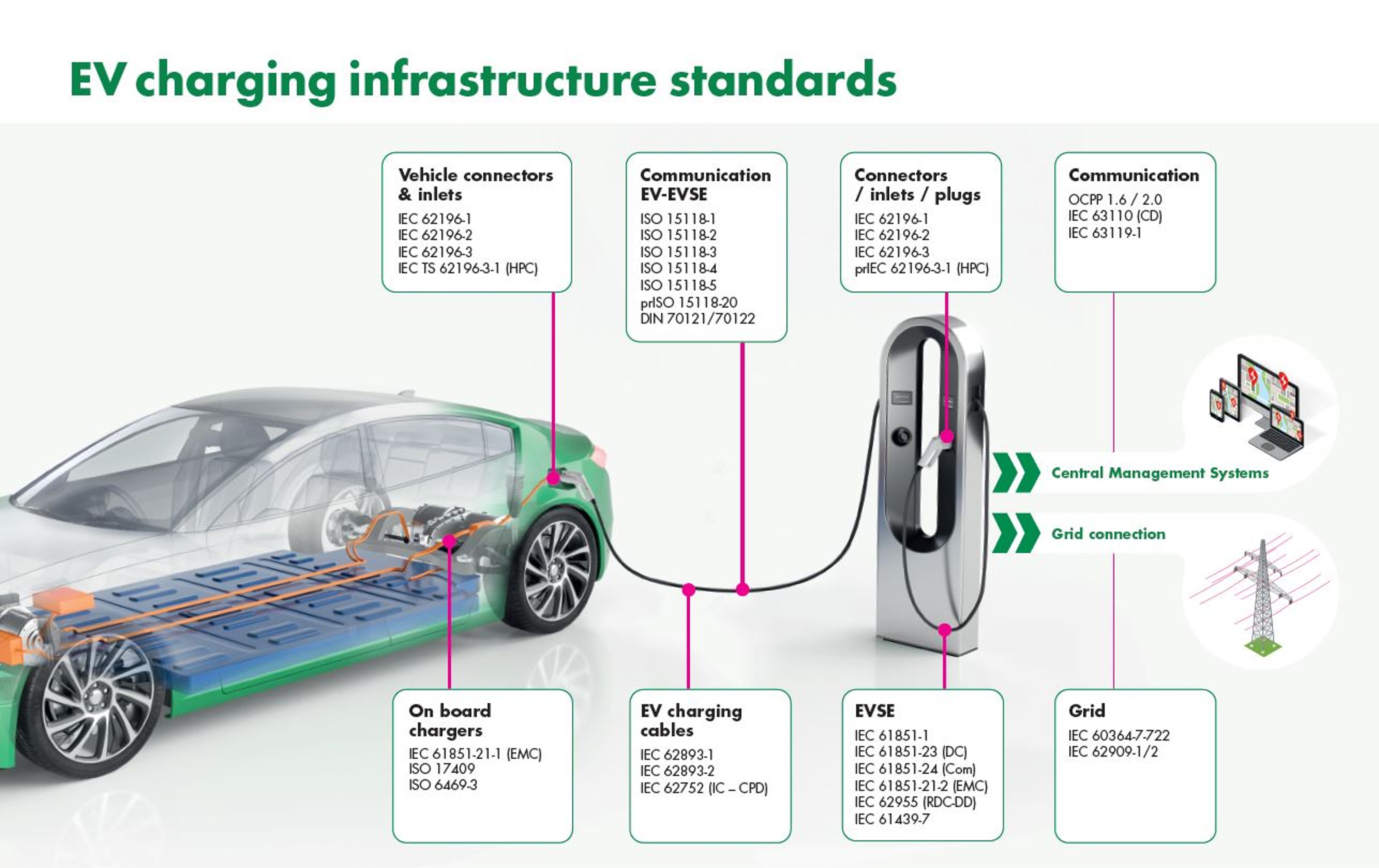
We can clearly see that EV charging is a complex intersection of power electronics, digital communication, and mechanical engineering. And despite the fragmented market (CCS vs. CHAdeMO vs. Tesla) in term of regional standards, there are similarities existed in technical standards and incoming project to unify the charging system.
- Future standards focus on bidirectional power transfer: ISO 15118-20 (the “2nd generation” HLC) introduces advanced features for bidirectional energy flow, allowing EVs to stabilize the grid or power homes (V2H) during peak hours.
- ChaoJi (The Unified Interface): A collaboration between the CHAdeMO Association and China’s GB/T. ChaoJi is a next-generation harmonized DC charging standard capable of ultra-high power (900kW+). It is designed to be backward compatible with both CHAdeMO and GB/T DC systems via adapters.