Overview of Unified Diagnostic Services Protocol
In vehicles, if something breaks, we need to get an understanding of what happened or is happening, so we able to provide appropriate measure. The term “diagnostic”, mean vehicle(ECUs) provide services(to output information on vehicle’s state), which then can be requested by us, to know the conditions, symptoms and problems of the vehicle and perform repair or configuration.
The diagnostic protocol UDS come in to the picture to provide standard ways of doing it. In this blog, we will go through an overview about Unified Diagnostic Services(UDS), which is unifiedly used by most of the OEM in automotive industry.
1. Diagnostic and usage
Target of vehicle diagnostic:
- Interrogate ECU’s fault
- Update, calibrate firmware of ECU
- Perform low level interaction with ECU’s hardware(e.g. on/off IO), self test operation
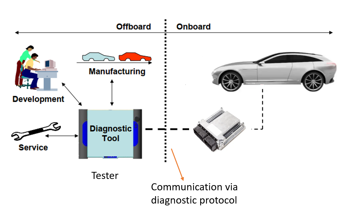
External tester tool use to connect to vehicle ECU via diagnostic plug/terminal, and communicate via diagnostic protocol like UDS. And diagnostic services are used in various use cases throughout lifetime of vehicle:
- Development testing and validation
- Manufacturing
- After sale servicing
⟹ For software development, diagnostic feature is mostly used for testing and validation.
>Diagnostic function shall be verified to be conformance with a specific standards(e.g. using Vector CANDiVa to create a conformance test suites and verify diagnostic function of the target ECU is fulfilled ISO14229 standards), and after that during software qualification or system verification & validation phase, diagnostic function shall be used as a medium to verify operation of other features.
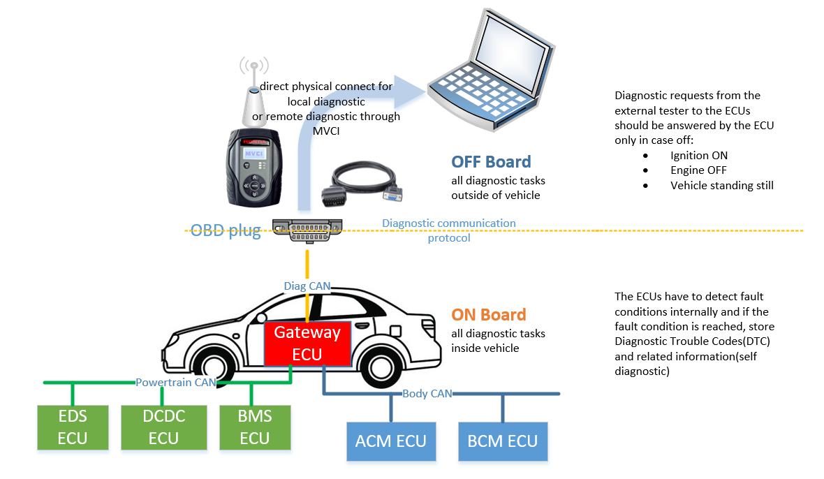
Beside diagnostic services provide for the external tester tool(OFF Board), vehicle also carry out self diagnostic during its operation(ON Board).
2. Diagnostic OSI model
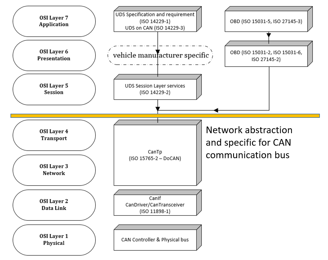
UDS protocol standard specifications are defined by International Organization for Standardization(ISO) in ISO 14229. There are 8 parts but in this introduction we only focus on PART 1:APPLICATION LAYER and PART 2: SESSION LAYER SERVICES for UDS application, the remaining is specific for different type of transmission medium(i.e. CAN, Ethernet, Flexray,…).
- ISO 14229-1: specifies data link independent requirements of diagnostic services, which allow a diagnostic tester (client) to control diagnostic functions in an on-vehicle electronic control unit (ECU, server) such as an electronic fuel injection, automatic gearbox, anti-lock braking system, etc. connected to a serial data link embedded in a road vehicle.
- ISO 14229-2: specifies common session layer services and requirements to provide independence between unified diagnostic services (ISO 14229-1) and all transport protocols and network layer services (e.g. ISO 13400-2 DoIP, ISO 15765-2 DoCAN, ISO 10681-2 communication on FlexRay, ISO 14230-2 DoK-Line, and ISO 20794-3 CXPI).
- ISO 14229-3: specifies the implementation of a common set of unified diagnostic services (UDS) on controller area networks (CAN) in road vehicles (UDSonCAN).
Beside that we also have some specifications on OBD, which specify information on emission related services and Diagnostic Trouble Code definition.
- ISO 15031-5: intended to satisfy the data reporting requirements of On-Board Diagnostic (OBD) regulations in the United States and Europe and any other region that may adopt similar requirements.
- ISO 15031-6: provides uniformity for standardized diagnostic trouble codes (DTC) that electrical/electronic On-Board Diagnostic (OBD) systems of motor vehicles are required to report when malfunctions are detected.
For this blog, we shall have some example on diagnostic over CAN, so some of the specification on lower layer CAN also to be considered:
- ISO 15765-2: specifies a transport protocol and network layer services tailored to meet the requirements of CAN‑based vehicle network systems on controller area networks as specified in ISO 11898‑1.
- ISO 11898-1: specifies the characteristics of setting up an interchange of digital information between modules implementing the CAN data link layer.
3. UDS protocol
3.1 Operation
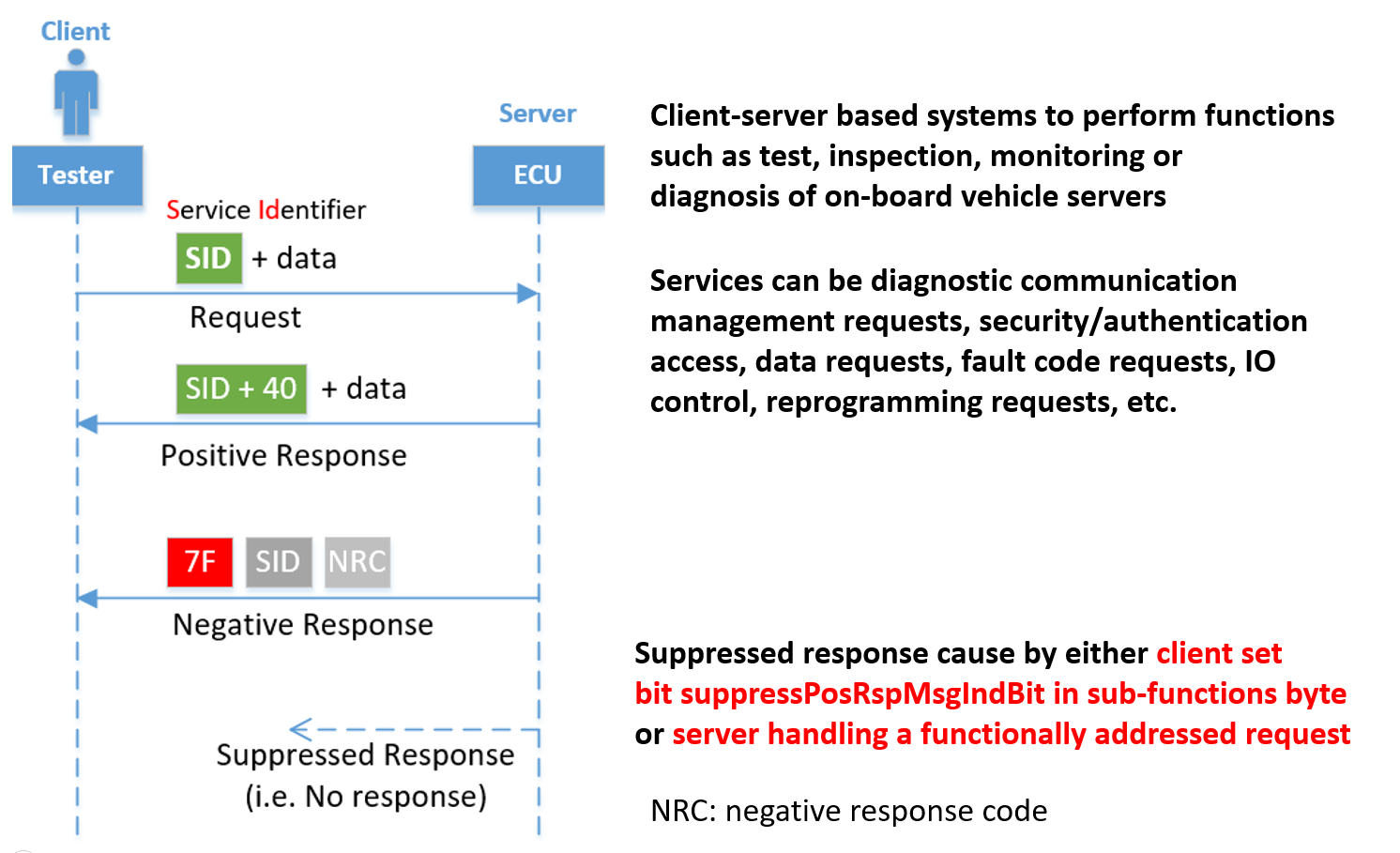
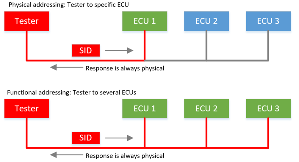
- The client: usually referred to as external test equipment, uses the application layer services to request diagnostic functions to be performed in one or more servers. Client can also be an ECU in vehicle(on-board tester), which is capable of carry out diagnostic request to other ECU (i.e. Gateway receive firmware updates(FOTA) and request flashing to other ECUs on the vehicle).
- The server: usually an ECU or a vehicle function(which is allocated in multiple ECU), uses the application layer services to send response data, provided by the requested diagnostic service, back to the client.
The server shall always confirm message transmission, meaning that for each service request sent from the client, there shall be one or more corresponding responses sent from the server either positive or negative.
The only exception from this rule shall be a few cases when functional addressing is used
or the request specifies that no response shall be generated.
In order not to burden the system with many unnecessary messages, there are a few cases when a negative response message shall not be sent even if the server failed to complete the requested diagnostic service.
NOTE: Negative response messages with negative response codes of SNS (serviceNotSupported), SNSIAS (serviceNotSupportedInActiveSession), SFNS (SubFunctionNotSupported), SFNSIAS (SubFunctionNotSupportedInActiveSession), and ROOR (requestOutOfRange) shall not be transmitted when functional addressing was used for the request message.
3.2 Protocol Data Unit structure
Application Layer diagnostic services format:
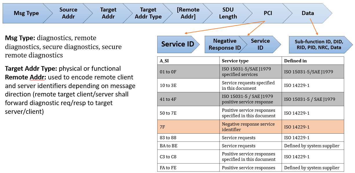
Message Type
diagnostics: direct diagnostic communication between diagnostic tester client and diagnostic server in the same network (no optional [Remote Address] field)
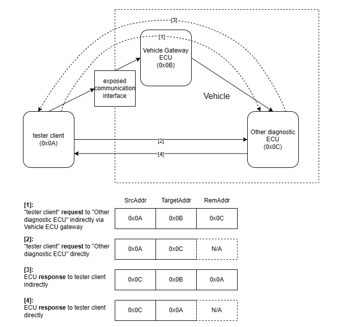
remote diagnostics: diagnostic services request/response from/to tester client([Source Address]) shall be routed to target diagnostic server([Remote Address]) via network gateway component([Target Address]) (e.g. Vehicle Gateway ECU).
secure diagnostics:Source Address: logical address of the node that send out diagnostic request or response.
Target Address: logical address of the node that receive diagnostic request or response, this could be functional or physical. In case of remote diagnostic type, this “Target Address” should be the address of local gateway node that interact with other network.
Remote Address: logical address of the node, which belong to other network that will receive diagnostic request or response from send node.
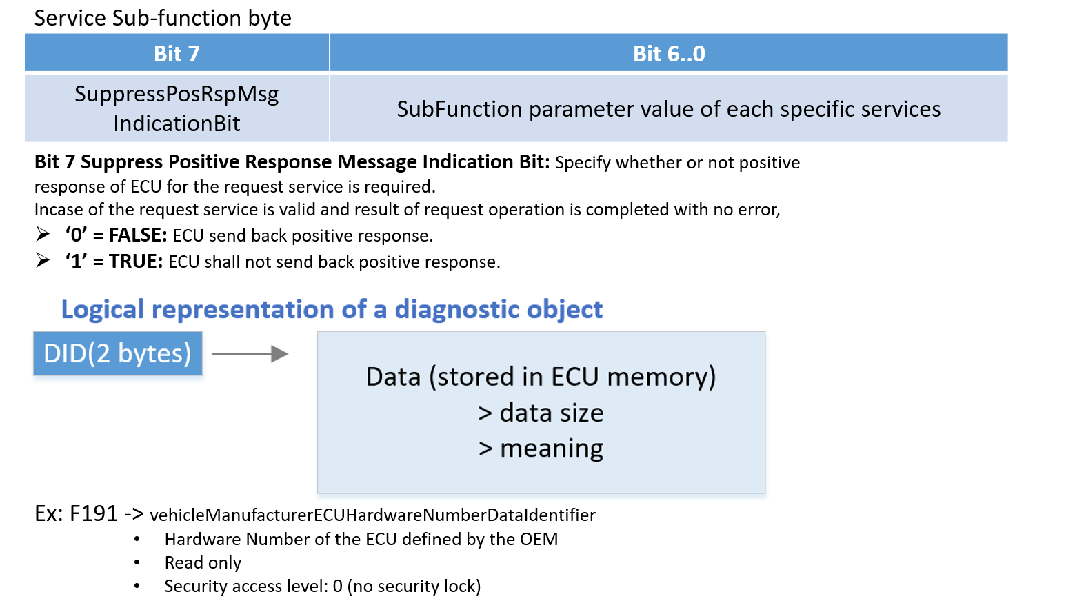
Sub-function byte, Data Identifier:
DIDs, PIDs, RIDs are similar since it is a logical presentation of non-volatile data(DID/PID) or function(executable operation RID).
Example of a CAN frame for UDS service:
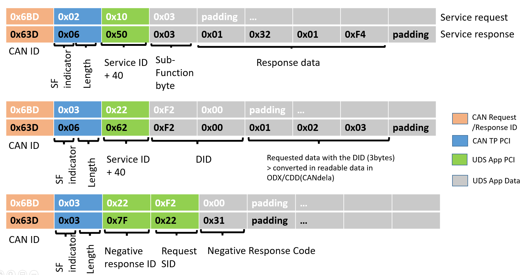
Several UDS services support sub-functions(SF) to further define the request functionality of the SID
➢ e.g. ECUReset, Session Change
Several UDS services support a Data Identifier(DID) to get access to data via a logical number(DID) which is used for the UDS communication
➢ e.g. Read & Write Data
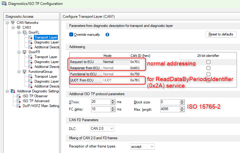
CAN TP PCI (protocol control information) is CAN transport layer PDU header information, specified by ISO 16572-2. CAN TP help break down and reassemble Application Layer UDS frame during transmission and receive, in case of application data can not be sent by a single CAN frame (i.e. classic CAN physical only support 8 bytes payload data).
Addressing:
 Example: EDS ECU in PT system of the vehicle shall has:
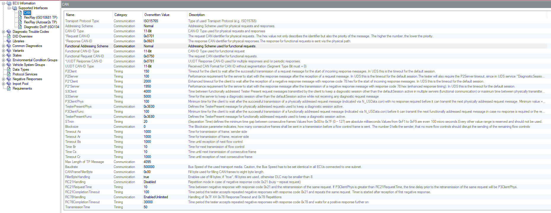
- physical address = 0x0A, shall has corresponding physical diagnostic request/response with CAN message ID value as 0x78A(req), 0x70A(resp) (base address for diagnostic function message in this CAN bus is 0x700 hence 0x7XX)
- 2 additional functional addresses: 0x22(0x722, in case of supporting OBD related services) and 0x3A(0x73A) for diagnostic services operation of all ECUs on the Power Train system.
Addressing schemes:
Depending on each project, some only support CAN message with 11 bit identifier(2.0A) other 29 bit(2.0B), different message addressing schemes for diagnostic source and target could be used:
| Scheme | Description | Example |
|---|---|---|
| Normal | CAN ID contains either source or target address. 2 CAN IDs for each ECU (diag request/response). ➢ n*2 msg ID used for diagnostic for n ECUs in the network | phys request: 0x78A phys response: 0x70A |
| Extended | CAN ID contains source address, first data (payload) byte contains target address. 1 CAN ID for diag request of all ECUs: base address + source address(tester), target of specific ECU is located in payload data. 1 CAN ID per each ECU for the response, ECU ID is in CAN ID and testerID is in payload data. ➢ n+1 msg ID used for diagnostic for n ECUs in the network | 11-bit: 0xNss, Data: 0xtt…. 29-bit: 0xNnNnNnss, Data: 0xtt…. |
| Normal Fixed (29-bit CAN IDs only) | CAN ID contains both source and target address. 2 CAN IDs for each ECU (diag request/response). | format: 0x03FFttss phys request: 0x03FF0102 phys response: 0x03FF0201 testerID: 0x01, ECU: 0x02 and 0x03FF is base for physical addressing |
| Mixed Addressing (29-bit CAN IDs only) | For ECUs in different subnets: CAN ID contains the local addresses, of which one is the gateway address; first data byte contains the remote address (local address in the other subnet, also called Address Extension AE). | 0x0CEAggss, Data: 0xtt… (0x0CEA is base for physical addressing) 0x0CDAggss, Data: 0xtt… (0x0CDA is base for functional addressing) |
gg: gateway address
ss: source address
tt: target address
Nn: any
Detail about addressing scheme can be read in ISO 15765-2.
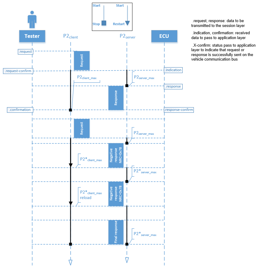
3.3 Message timing
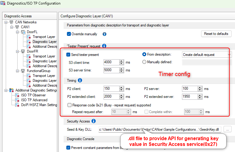
For session layer of UDS, there are no special operation beside timing of handling request/response during communication. In general, we have to configured following timers:
⮚ Tester:
- P2Client: Timeout value for the client to wait after the successful transmission of a request message till the start of incoming response message.
- P2Client_max: is the initial/default value of P2Client
- P2*Client_max: enhanced timeout for the client to wait after the reception of a negative response message, with negative response code 0x78(requestCorrectlyReceived-ResponsePending) for the start of next incoming response messages.
- S3 client time: Time the diagnostic client (=tester) should wait before sending a tester present request.
⮚ ECU:
- P2Server: performance timer of ECU, and is either loaded with P2Server_max or P2*Server_max value.
- P2Server_max: server either process the request and send back a response in time or the request processing is still going and the timeout(P2Server_max value) occur then server send back a negative with NRC=0x78 for “requestCorrectlyReceived-ResponsePending” to notify about pending final response.
- P2*Server_max: performance requirement for the server to start after the transmission of a negative response message with negative response code 0x78. In case the server can still not provide the requested information within the enhanced P2*Server_max, then a further(number of time depend on configuration) negative response message with negative response code 0x78 shall be sent again.
- S3 server time: Timeout in the diagnostic server for leaving a non-default session.
- P4Server: is performance requirement time, which is period between the reception of a request and the start of transmission of the final response(which can be either a positive response or negative response with NRC is not 0x78).
In case of a request to schedule periodic responses, the initial Unacknowledged Segmented Data Transfer(USDT) positive or negative response that indicates the acceptance or non-acceptance of the request to schedule periodic responses shall be considered the final response.
If P4Server_max is the same as P2Server_max, this means that a negative response with negative response code 0x78 is not allowed for that service or data- P4Server_max: is the maximum value of P4Server
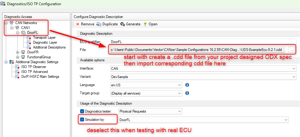
Configuration of underlying CAN TP protocol for diagnostic can usually be founded in .cdd(CANdela Diagnostic Description) file if your project use Vector software tool chain in development. 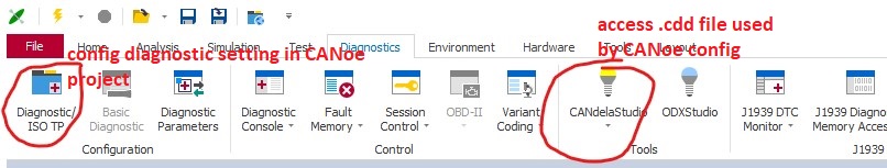
4. Services
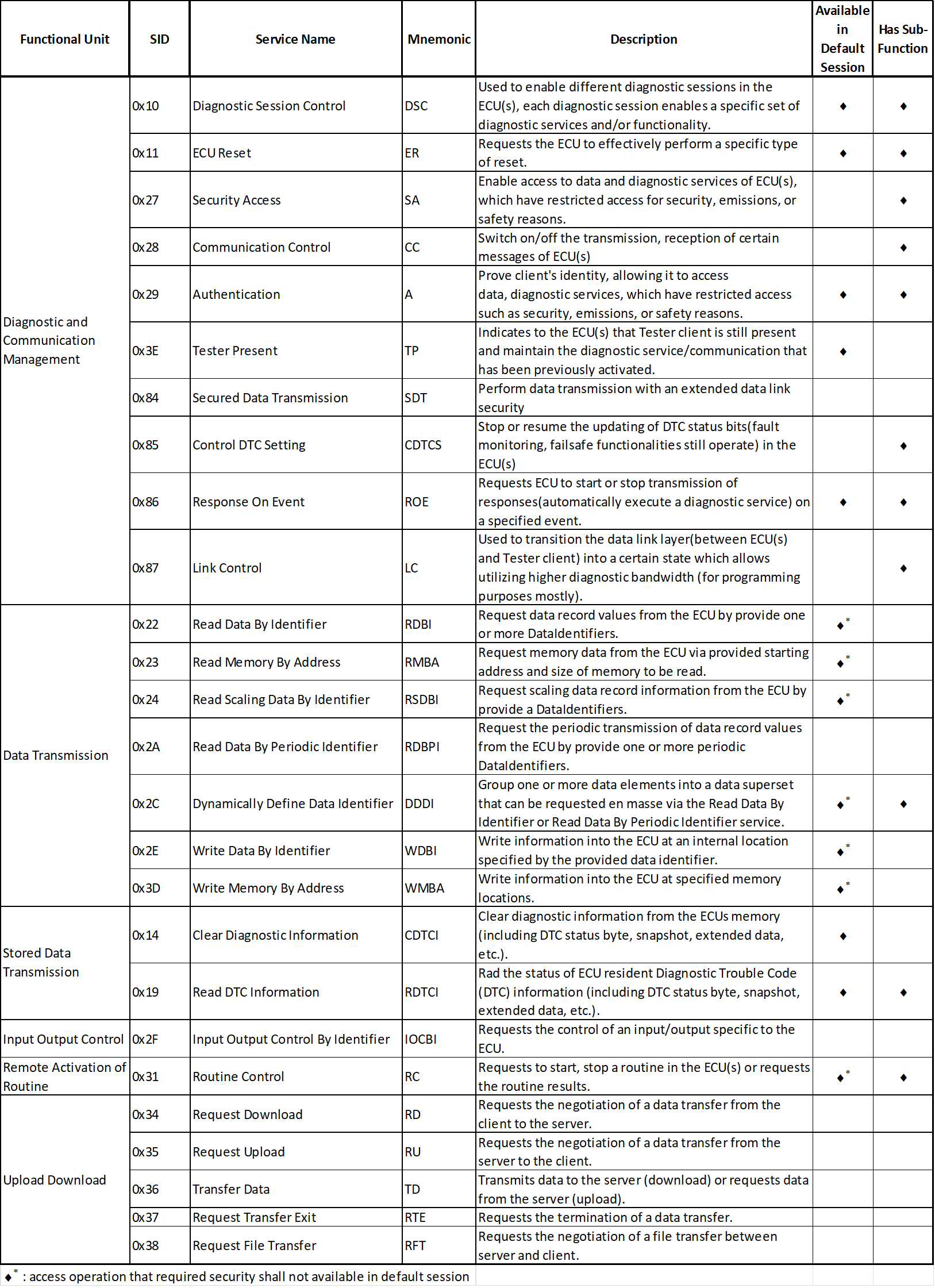
4.1 Service list
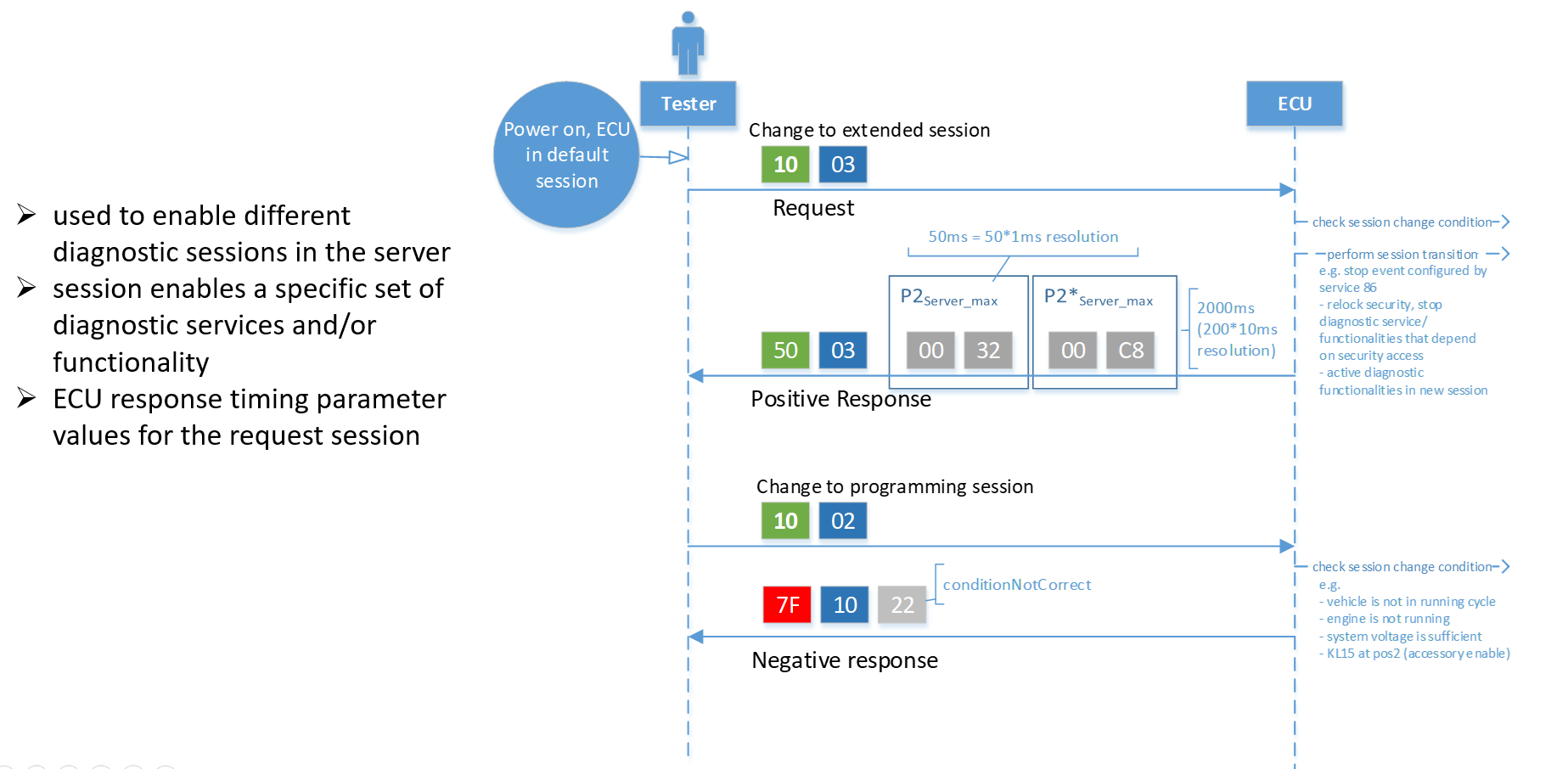
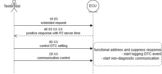
4.2 Example - Diagnostic Session Control service operation
General service handling: mandatory for all service request, validation steps are specified in below figure. Depend on choice of the implementation, not all of the NRC check are required.
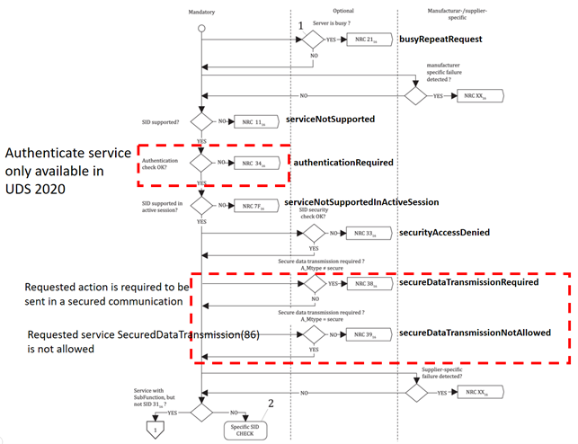
1: diagnostic request cannot be accepted because another diagnostic task is already requested and in progress by a different Tester client
2: refer to the response behaviour (supported negative response codes) of each service
General service sub-function handling: mandatory for all request service with SubFunction parameter, validation steps are specified in below figure.
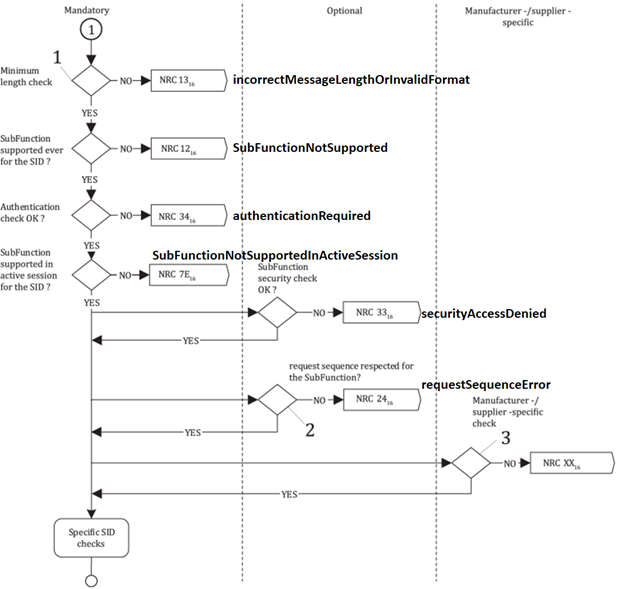
1: at least 2 (SID+SubFunction Parameter)
2: if SubFunction is subject to sequence check, e.g. LinkControl or SecurityAccess
3: refer to the response behaviour (supported negative response codes) of each service
Specific handling operation for Diagnostic Session Control service(0x10):
5. Session
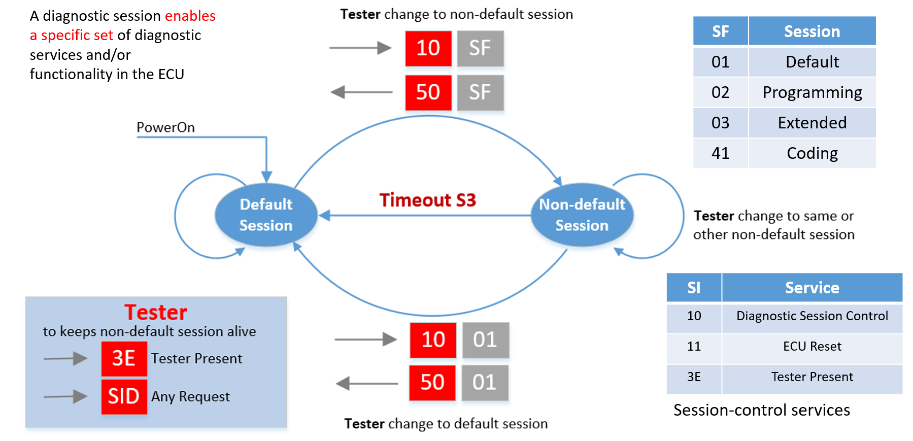
There shall always be exactly one diagnostic session active in a server. A server shall always start the default diagnostic session when powered up. If no other diagnostic session is started, then the default diagnostic session shall be running as long as the server is powered.
The set of diagnostic services and diagnostic functionality in a non-default diagnostic session (excluding the programmingSession) is a superset of the functionality provided in the defaultSession.
>Normal operation of the ECU shall be retained when executing diagnostic services within the default, extended session.
Transition to non-default session (from either default or other non-default session):
- Stop all event configured by ResponseOnEvent(0x86) in default session.
- Security shall be relocked, locking of security access shall reset all diagnostic functionality, which depend on unlocked security access.
- Other diagnostic functionality that not depend on security access shall be maintained.
Transition back to default session:
- Reactive events of ResponseOnEvent(0x86).
- Any other active diagnostic functionality that is not supported in the defaultSession shall be terminated.
S3Server Timer < timeout session: Time for the server to keep a diagnostic session other than the defaultSession active while not receiving any diagnostic request message.
Change to non-default session > start S3Server Timer: The S3Server Timer is also restarted upon the reception of a diagnostic request message that is not supported by the server/ completion of a services.
6. Security Access & Authenticate
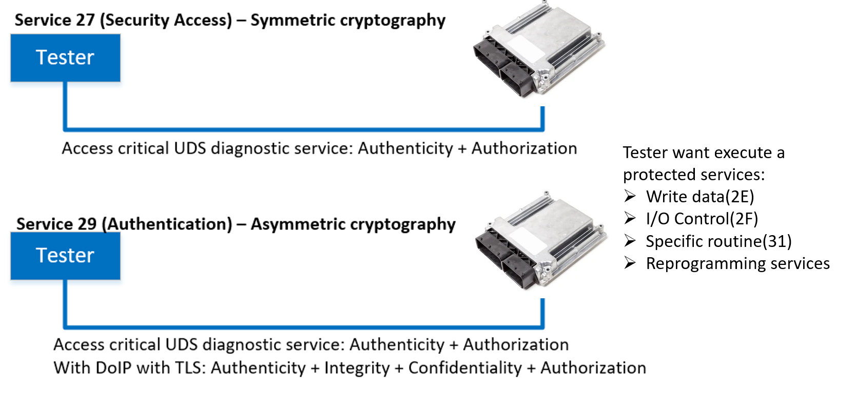 Service 0x27: Tester unlock ECU access using seeding key process > access to protected functionality like specific routine related to memory modification, programming.
Service 0x29(new for UDS ver2020): Tester authenticate its role by using certificate base PKI > might required to connect/access to OEM server to get certificate.
6.1 Security Access operation
Services Security Access(0x27) provide a means to access data and/or diagnostic services, which have restricted access for security, emissions, or safety reasons. Improper routines or data downloaded into a server could potentially damage the electronics or other vehicle components or risk the vehicle’s compliance to emission, safety, or security standards. The security concept uses a seed and key relationship(asymmetric).
Another thing to remember, with AUTOSAR, there is only one Security Access Level state machine independent of how the Tester communicates with the ECU (i.e. ECU security access is opened with CAN connection then another Tester can have directly security access via DoIP connection without have to re-request security access).
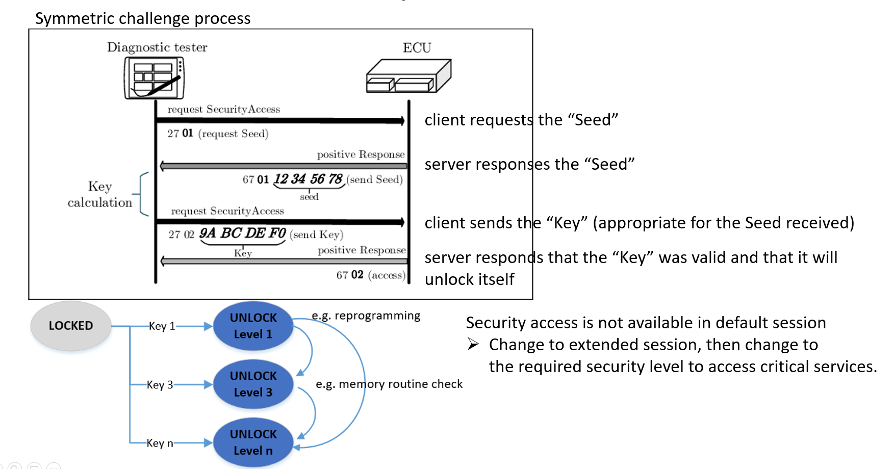 ‘requestSeed’ SubFunction parameter value: odd value
‘sendKey’ SubFunction parameter value: equal requestSeed value + 1 ⟹ even value
6.2 Authentication
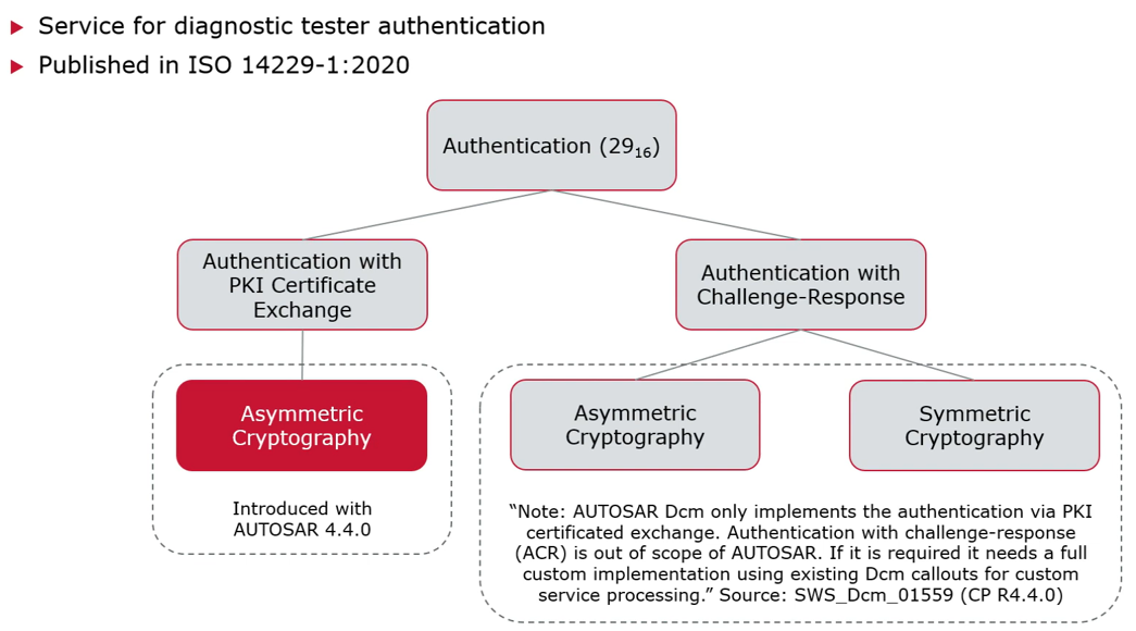 The purpose of this service is the same as Security Access service(0x27), authorization via user roles(supplier, development, after sales,…) instead of level as 0x27, and Authentication service(0x29) security concept either base on:
- PKI certificate exchange and use asymmetric cryptography (Introduced in AUTOSAR 4.4.0).
- Challenge-response without PKI and asymmetric or symmetric cryptography (Out of scope of AUTOSAR, required to be custom implemented in DCM).
- With AUTOSAR, authentication state machine per physical connection.
7. Fault & DTC
7.1 Fault memory
If any fault will happen in during operation of the ECU, it will store this fault code, fault status, snapshot data and some extended data record which will help the diagnostic engineer to know the root cause easily and repair the vehicle.
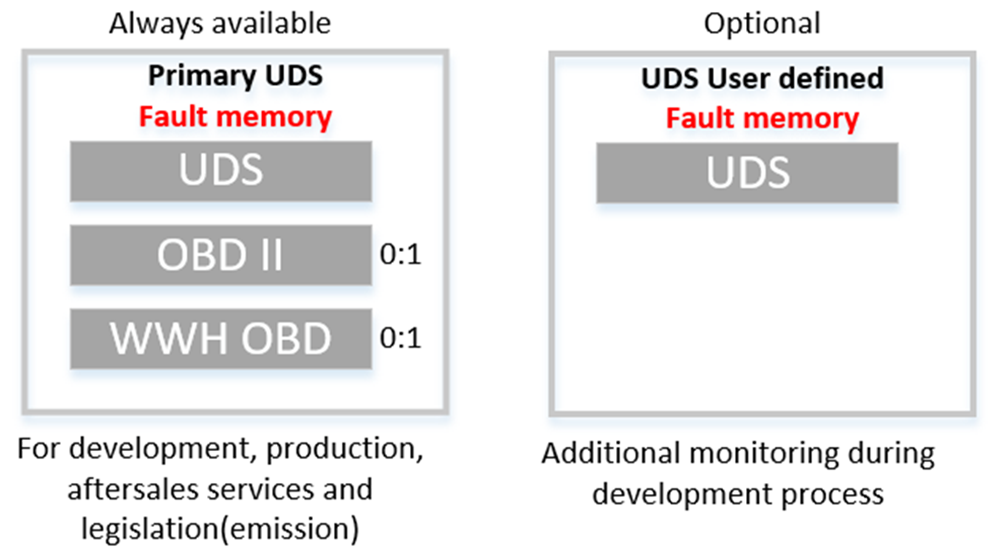
Fault memory: storage location for fault-related information during ECU operation and later to be read by Tester during OFF Board diagnostic operation.
There shall be:
⮚ Primary fault memory for all the UDS code and legislated fault of OBD(ECU has emission-related feature).
⮚ Additional UDS User defined fault code (optional during development process and not for production).
Attributes of Faults code(Diagnostic Trouble Code - DTC):
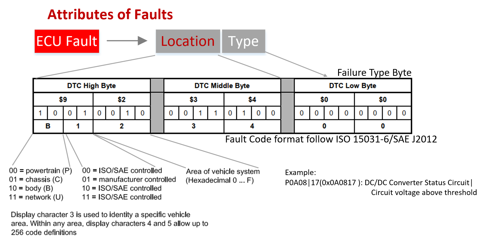 A DTC defines unique identifier mapped to diagnostic event(of DEM) and can be interrogated later by Tester(through DCM).
- The first byte shall address the location of fault, basically the location of ECU in vehicle(e.g. Powertrain, Body,..) and whether this DTC is defined by ISO spec or manufacturer.
- The second byte show the failed component/system.
- The last byte show the failure category and subtype, detailed what kind of fault had occurred.
So with each logical DTC number following data shall be associated to it:
DTC Status Byte:
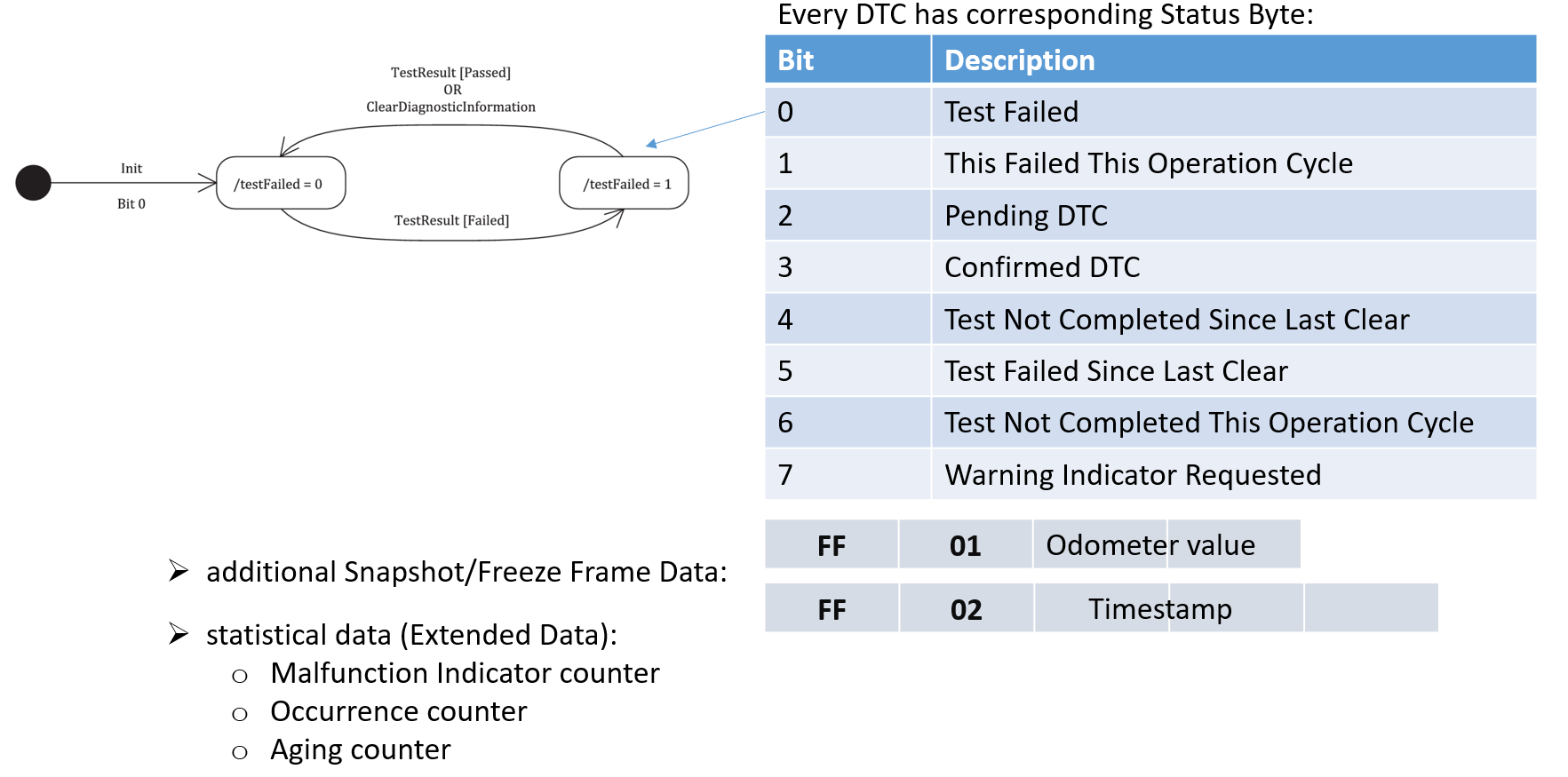
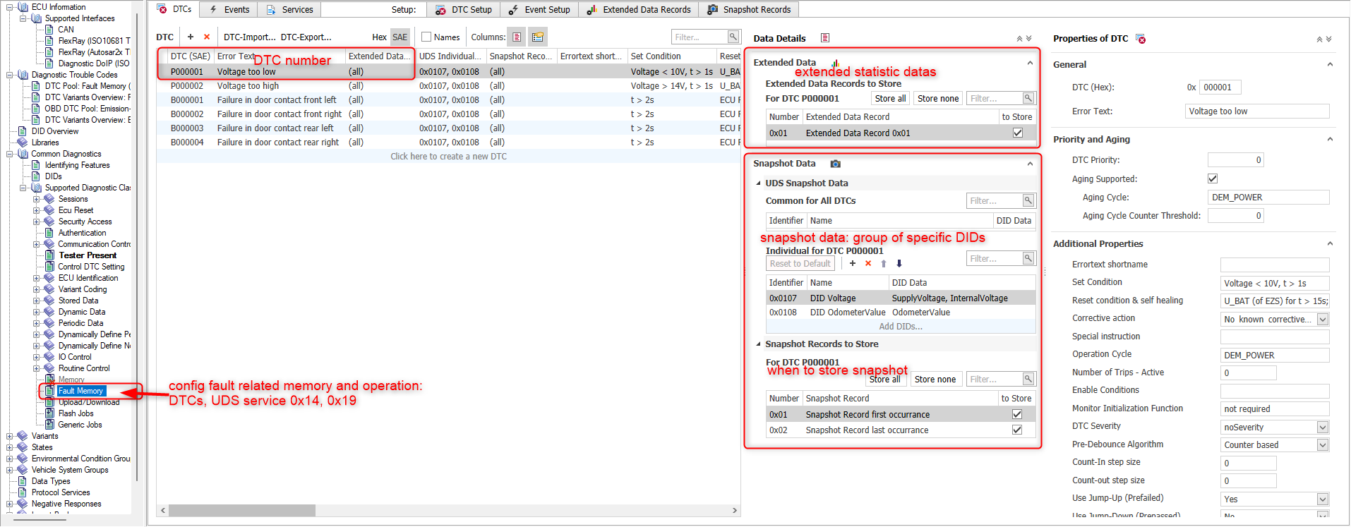
DTC Snapshots: are specific data records(DIDs) associated with a DTC, that are stored in the server’s memory. The typical usage of DTC Snapshots is to store data upon detection of a system malfunction. The DTC Snapshots will act as a snapshot of data values from the time of the system malfunction occurrence.
DTC Extended Data: is to store dynamic data(statistic) associated with the DTC
- DTC B1 Malfunction Indicator counter which conveys the amount of time (number of engine operating hours) during which the OBD system has operated while a malfunction is active.
- DTC occurrence counter, counts number of driving cycles in which “testFailed” has been reported.
- DTC aging counter, counts number of driving cycles since the fault was latest failed excluding the driving cycles in which the test has not reported “testPassed” or “testFailed”.
- specific counters for OBD (e.g. number of remaining driving cycles until the “check engine“ lamp is switched off if driving cycle can be performed in a fault free mode).
- time of last occurrence (etc.).
- test failed counter, counts number of reported “testFailed” and possible other counters if the validation is performed in several steps.
- uncompleted test counters, counts numbers of driving cycles since the test was latest completed (i.e. since the test reported “testPassed” or “testFailed”).
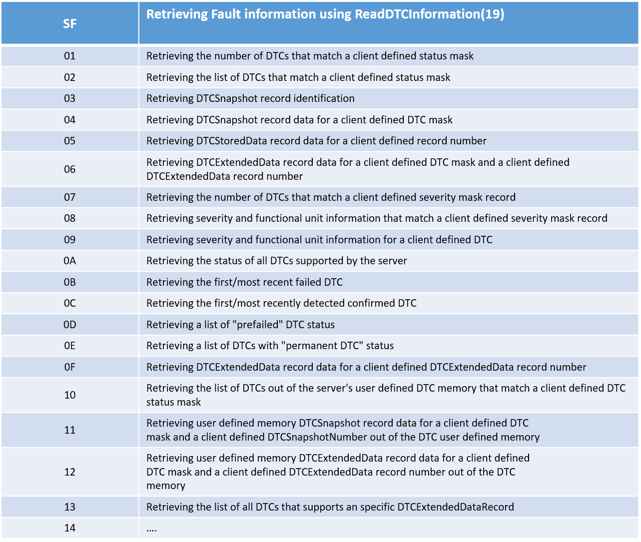
To retrieving DTC information, we use UDS service 0x19:
7.2. Data Identifier
A Data Identifier (DID) is is logical number used to address specific data storage location available in the ECU memory. DID is used for various diagnostic use-cases such as:
- Measurement, Dynamic, Live Data
- Stored Data
- Identification
- IO Control
- ECU Configuration, Variant Coding
- Freeze Frame / Snapshot Data
- …
Normally some Data Identifier(DID)s shall be configured as related to specific DTC and a snapshot of their value is stored when DTC is logged.
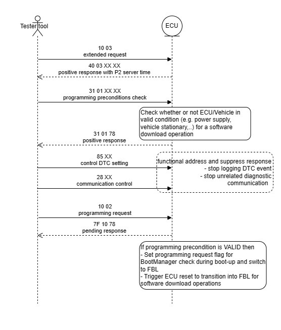
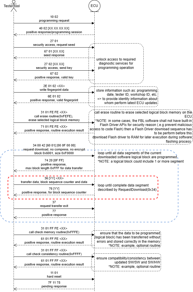
8. Flashing (reprogramming)
A list of diagnostic services shall be used in flashing operation to provide a defined sequences/interfaces, that handle software update process(i.e. pre-programming state transition, communication interface preparation, transmission and programming of received data into flash memory).
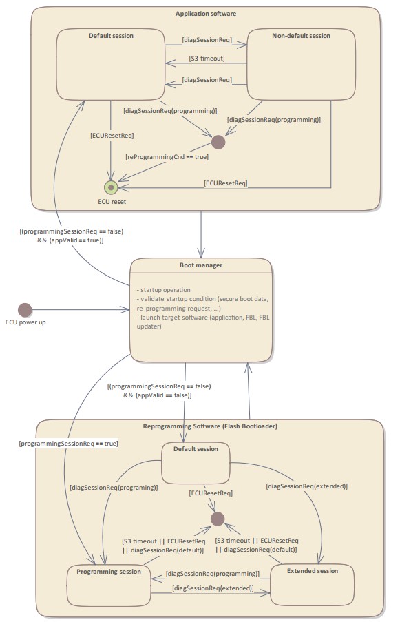
Diagnostic software shall support services:
- to trigger the transition from Application to Reprogramming state.
- to download updated software(split into multiple data packets) from Tester entities.
- to erase and write data into flash memory.
Programming sequence is divided into two programming phases.
Programming phase 1(mandatory): used for programming below software/data
- bootloader software
- application software
- application data
The programming sequence can be divided into 3 sections: pre-programming, programming execution, post-programming
Programming phase 2(optional): can be triggered by FBL and perform when ECU boot-up into application such as:
- some additional ECU identification update,
- clear old diagnostic fault,
- and adaption, coding data need to be written into ECU after completed a application software update.
Below is a example sequence of diagnostic services that shall be called during programming operation (Phase 1).
9. Configuration and Calibration (adaption/coding DIDs)
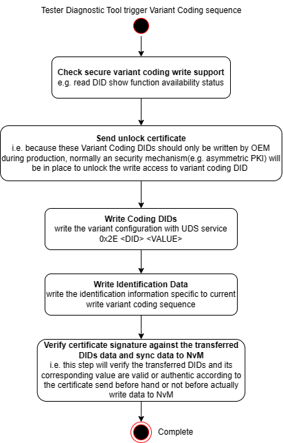
Coding DIDs is used to toggle on/off specific functionalities of the ECU to adapt it to different ECU specific HW platform or line of vehicle. Normally Variant Coding DIDs shall be configured during End-Of-Line production with a secure variant coding write sequence as below.
Calibration DIDs is used to tuning the ECU operation, e.g. when adapting its configuration to surrounding conditions such specific operating environment, other vehicle equipments(sensor, actuator characteristics),… The write Calibration DIDs sequence could be similar to above variant coding one.
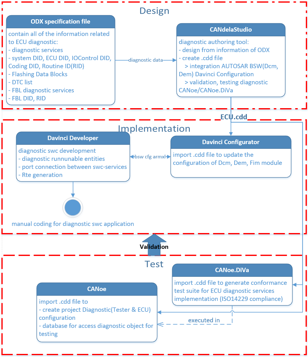
10. Diagnostic function development
When it comes to development the diagnostic functionalities of an actual ECU project, how it should be carried-out? You can refer to below diagram.
This just an example, different project with different tool-chains might be slightly variate. But still you have to has:
- OEM diagnostic specification, project dependent diagnostic specification ⟹ requirement and is realized in Open Diagnostic eXchange(ODX) format database file such as .cdd, .pdx, .odx
- Development tool to view/modify ODX file or possibly parsing the file content into corresponding configuration data ⟹ configuration of classic AUTOSAR module like DEM, DCM, FIM.
- Design and implementation of diagnostic application (SWCs).
- Diagnostic testing tool to parse the ODX file to create validation environment manually or automation ⟹ ODX file is used as reference data for V&V operation.